


– 7 –
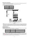
RECEIVER CABLE CONNECTIONS
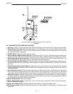
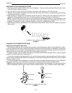
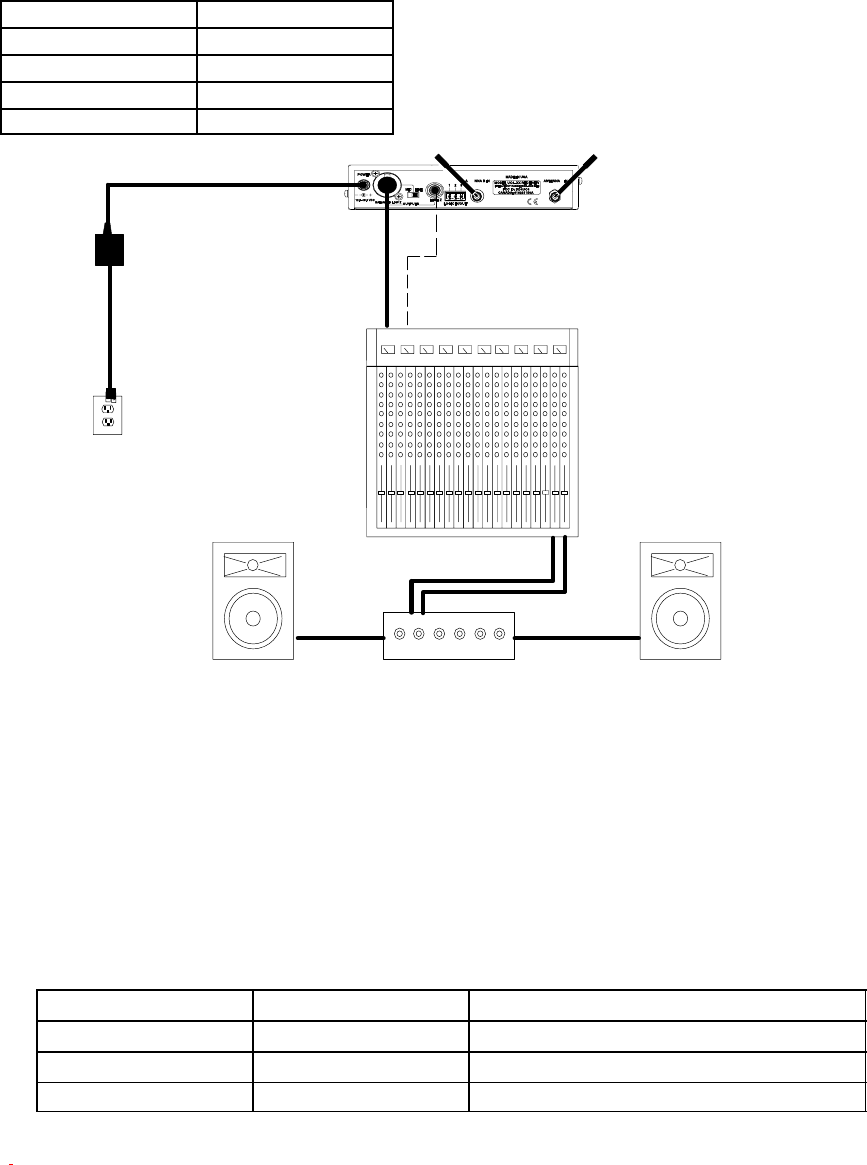
1. Connect the receiver output to the mixer or amplifier input, using a standard audio cable with a female 3–pin XLR
connector or 1/4” phone plug. Refer to Figure 5.
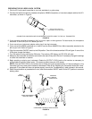
2. Connect the AC power adapter to the POWER jack on the rear panel of the receiver.
3. Plug the AC adapter into an AC power source.
Power Supply Model Power Type
PS40 90–120 VAC, 60 Hz
PS40E 230 VAC, 50/60 Hz
PS40UK 230 VAC, 50/60 Hz
PS40J 100 VAC, 50/60 Hz
AC POWER
SOURCE
AUDIO MIXER
AMPLIFIER
LOUDSPEAKER
LOUDSPEAKER
DC POWER
SUPPLY
TYPICAL UC4 RECEIVER CABLING CONFIGURATION
FIGURE 5
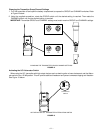
NOTE: If a receiver is rack mounted, RF performance can be improved by remotely locating the antennas. Diversity
performance can be improved by placing one or both antennas at a remote location and separating them by at least
1.5 meters (60 in.). Use UA825 or UA850 Extension Cable kits or other low–loss cable (RG8 or equivalent) with
remote antennas. Do not use the supplied 1/4 wave antennas at remote locations. Use only UA820A 1/2 wave an-
tennas for remote installation.
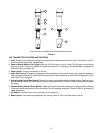
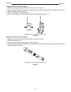
TRANSMITTER SETUP
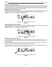
Checking the Transmitter Battery
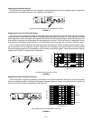
Turn the transmitter ON/OFF switch to the ON position and verify that one of the LEDs glow. The amount of battery
life remaining is indicated by which LED is lit, as shown in the following table:
Transmitter LED Color Receiver LED Color Remaining Transmitter Operating Time
Green –– 2 to 8 hours
Amber –– 45 minutes to 2 hours
Red Red 45 minutes or less
*Estimated operating time assumes the use of a fresh 9V alkaline battery.
NOTE: If extended performance time is required, use an Ultralife 9V lithium battery, which can last more than twice
as long as an alkaline battery. A rechargeable 8.4V nicad battery will cause the indicators to change more quickly
than if a 9V alkaline battery is used. Carbon-zinc and zinc-chloride batteries will not provide adequate power and are
not recommended. Actual times depend on the type and brand of battery used.