


– 13 –
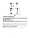
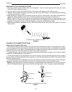
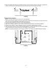
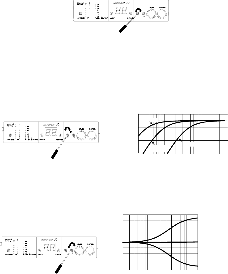
Adjusting the Equalizer Setting
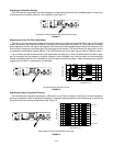
The UC4 receiver incorporates a two band equalizer to help adjust the sound of the wireless system to match that
of other wired and wireless products in an installation. See Figure 17.
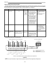
ADJUSTING THE UC4 RECEIVER EQUALIZER SETTING
FIGURE 17
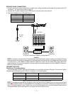
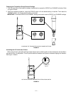
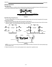
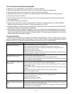
Adjusting the Low–Cut Filter (High Pass)
The low–cut (or high–pass) filter allows all frequencies above its cutoff point to pass from filter input to filter output
without attenuation, while frequencies below its cutoff point are attenuated. See Figure 18. The cutoff point is defined
as the frequency at which the signal has dropped 3 dB relative to the flat bandpass region. Below the cutoff point, the
filter exhibits increasingly more attenuation as the frequency level drops. The rate at which this attenuation occurs
is expressed in decibels per octave (dB/oct). The UC4 Receiver has a one–pole, low–cut filter of 6 dB per octave.
Low–cut filters are used to attenuate the audio signal when low frequency noise or excessive proximity effect is pres-
ent. For example, the low–frequency vibration caused by wind, footsteps, and vehicular traffic can be transmitted
through microphone stands to the microphone, and from there to the sound system. These low frequencies, typically
ranging from 5 to 80 Hz, are generally not desirable.
-10
-8
-6
-4
-2
0
+2
20 100 1,000 5,000
FREQUENCY (Hz)
FULL CW
50% ROTA-
TION
FULL CCW
AMPLITUDE (dBV)
ADJUSTING THE LOW CUT FILTER
FIGURE 18
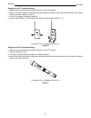
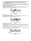
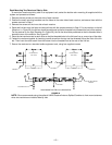
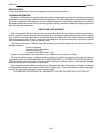
Adjusting for High–Frequency Shelving
The fixed frequency equalizer produces a 6 dB boost or cut at 5 kHz and above. See Figure 19. High–frequency
shelving is extremely useful for boosting flat frequency response, softening sibilant vocal microphones, or enhancing
the sound of off–axis lavalier microphones. See Figure 19.
200
-10
-8
-6
-4
-2
0
+2
+4
+6
+8
+10
1,000 10,000
20,000
FREQUENCY (Hz)
FULL CW
FULL
CCW
50%
ROTATION
AMPLITUDE (dBV)
ADJUSTING FOR HIGH FREQUENCY SHELVING
FIGURE 19