


ENGLISH
ENGLISH
– 18 –
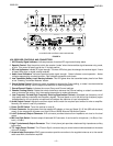
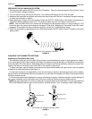
LOGIC CONNECTION SPECIFICATIONS
The logic capability of the UC4 receiver provides two functions: transmitter status indication (which can be used to
signal and control other events) and transmitter low battery indication. The various logic functions and their applica-
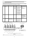
tions are presented in the following table. Refer to Figure 28 below for pin mapping.
Pin No. Function Transmitter Status Logic Level Typical Applications Connections
1 Signals or controls
other events.
On
Off
Low (0V)
High (+5 V)
100 mA of
current
sinking
provided.
• Drives a remote LED.
• Provides remote indica-
tion of transmitter status
when used with a Room
Control System (i.e.,
Crestron or AMX)
• Activates external equip-
ment (equalizer, signal
processor, loudspeakers,
etc.) when used with a
Room Control System.
• Transmitter status control
muting/unmuting of an in-
put channel on automatic
mixer. Used with auto-
matic mixers, such as
Shure Model SCM810
Tie the transmitter status
pin to podium mic mute in-
put terminal on the automat-
ic mixer
Tie receiver logic ground to
mixer logic ground.
2 Logic Ground* –– –– –– Make all logic ground con-
nections to this pin, includ-
ing the power supply
ground of external logic cir-
cuitry. To avoid switching
noise, do not connect logic
ground to audio, chassis, or
rack grounds.
3 Remote indication of
transmitter battery
status.
Good Battery (1–8 hours of
battery life remaining)
Low Battery (1 hour of less
of battery life remaining)
Low (0 V)
High (+5 V)
• Drives a remote LED to
light when battery is low.
• Indicates low transmitter
battery status on remote
control panel when used
with a Room Control
System.
*Logic ground is distinct from UC4 audio ground.
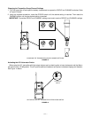
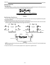
LOGIC GROUND
MUTE
LOGICGATE 1
MUTE 1
GATE 3
MUTE 3
GATE 5
MUTE 5
GATE 7
MUTE 7
GATE 2
MUTE 2
GATE 4
MUTE 4
GATE 6
MUTE 6
GATE 8
MUTE 8
GROUND
SCM810 MIXER DB 25 LOGIC CONNECTOR
UC4 LOGIC CONNECTOR
OVERRIDE 5 OVERRIDE 7OVERRIDE 1 OVERRIDE 3
OVERRIDE 2 OVERRIDE 4 OVERRIDE 6 OVERRIDE 8
PIN 1: TRANSMITTER STATUS OUT
PIN 2: LOGIC GROUND
PIN 3: TRANSMITTER LOW BATTERY
TYPICAL UC4 CONNECTIONS TO SCM810 MIXER LOGIC CONNECTOR
FIGURE 28
NOTE: For more information on logic functions, please contact the Shure Applications Department.