


I
L....
-- -- -
damit der Quarzoszillator nicht
schwingt. Der Wahlschalter der Be-
triebskontrolle wird auf Stellung "Fre-
quenz" gestellt. Der Abgleich erfolgt
durch Drehen der Spulenkerne von Lu,
L13,L12auf maximalen Ausschlag am
Betriebskontrollinstrument. Ll1wird auf
Nulldurchgang des Instrumentes abge-
glichen, das an den Meßpunkten B +
C angeschlossen ist. Während des Ab-
gleichs ist die Meßsenderspannung
immer so einzustellen, daß der Zeiger
des Betriebskontrollinstrumentes nicht
im roten Feld steht. Nach dem Ab-
gleich wird die Meßsenderspannung
erhöht, bis die Spannung am Betriebs-
kontrollinstrument steht. Für diesen
Begrenzer-Einsatzpunkt soll nicht mehr
als 10 mVEingangsspannung am Meß-
punkt A erforderlich sein.
Abgleich des freilaufenden Oszillators:
Es werden zunächst der Meßsender und
das Nullinstrument entfernt. Die Meß-
punkte Bund C werden kurzgeschlos-
sen, damit die Regelspannung nicht
wirksam ist. Mit P3 wird die Spannung
zwischen den Meßpunkten 0 und E so
eingestellt, daß keine Differenz mehr
besteht. Der Frequenzumschalter S2
wird auf die hohe Frequenz eingestellt.
Durch Verdrehen des Eisenkerns von
L, wird die Frequenz richtig eingestellt.
Die Abgleichelemente des bis zum HF-
Ausgang folgenden Verstärkers L2, L3,
L4,CO" CO9,C7', CH, C77und C7. wer-
den auf maximale Ausgangsspannung
abgeglichen. Die Ausgangsspannung
soll 7,6
- 8 V betragen und wird am
besten mit einem Meßempfänger (FHM
88, Wandel &.Goltermann) kontrolliert.
Die Frequenz wird mit dem Frequenz-
messer (WIK, Rohde &.Schwarz) über-
prüft und auf :t 10 kHz genau einge-
stellt. Danach wird S2 auf die tiefere
Frequenz eingestellt. Mit C,. wird auch
diese Frequenz auf :t 10 kHz genau
eingestellt. Anschließend wird kontrol-
liert, ob die Ausgangsspannung bei
beiden Kanälen gleich ist. Sollte das
nicht der Fall sein, muß der Abgleich
des HF-Verstärkers korrigiert werden.
Nun wird der Kurzschluß zwischen den
Meßpunkten Bund C aufgehoben und
der Quarzoszillator in Betrieb genom-
men. Der Kern von Ln wird so weit
hineingedreht, bis der Quarzoszillator
anschwingt. Dieser Zustand ist da-
14
---
trol instrument of the transmitter. Ll1
must be tuned to zero indication on
the mid-zero instrument. Whilst align-
ing the signal generator voltage should
be maintained such that the pointer of
the control instrument does not reach
the red field. After finishing the IF
alignment the output signal of the RF
generator should be increased until
the voltage indication at the control
instrument does not increase any fur-
ther. To reach this point where limiting
starts should not require more than
10 mV at test point A.
Alignment of the free-running
C
oscillator:
First detach the RF signal generator
and the mid-zero instrument. Then
short-circuit the test points Band C
to make the control voltage ineffective.
By means of P3 adjust the voltage be-
tween the testpoints 0 and E such that
there is no difference. Switch the fre-
quency change-over switch to the
higher frequency. By turning the iran
core of L, the frequency can be set to
the right value.
All tuning elements of the following
stages L2, L L4, Co., CO9,C71, CH and
C77 are tuned to maximum output volt-
age which should be 7.6 to 8 V and can
be checked by means of the frequency
deviation meter (FHM 88, Wandel &.
Goltermann). The frequency is checked
with the frequency meter (WIK, Rhode
&.Schwarz) and adjusted with a toler-
ance of :t 10kHz. Thereafter switch to
the deeper frequency which shouid be
adjusted by C,. with :t 10 kHz toler-
ance. Finally it is necessary to check
whether the output voltage is the same
(
I)
for both frequencies. If a difference
occurs correct the alignment of the
RF amplifier.
Disconnect the short-circuit between
test points Band C and start the crys-
tal-controlled oscillator. The core of
Ln is screwed so far into the coil until
the oscillator works. The working con-
dition is clearly recognizable because
the IF signal occurs and the control
instrument shows a deflection in po-
sition "FREQ". The core of Ln is tuned
such that the crystal-controlled oscil-
lator works weil in both positions of
switch S2. L'5 and L,o are tuned to give
maximum IF signal and Lu must be
durch zu erkennen, daß die Zwischen-
frequenz entsteht und das Betriebs-
kontrollinstrument in Stellung Fre-
quenz einen Ausschlag zeigt. Der Kern
von Ln wird so eingestellt, daß der
Quarzoszillator in beiden Stellungen
von S2 sicher schwingt. L'5 und L,o wer-
den auf maximale ZF-Amplitude ab-
geglichen, auch Lu wird noch einmal
nachgestimmt. Eine Kontrolle der Be-
triebsfrequenz ist noch erforderlich,
weil die ZF vom genauen Wert abwei-
chen kann. Dazu verdreht man den
Kern von L'D so lange, bis die Soll-
Betriebsfrequenz erreicht ist. Ll1, L12,
(
L13 werden nochmals auf max. ZF-
( Amplitude abgeglichen. Die Frequenz
auf beiden HF-Kanälen muß dann auf
:t 1 kHz stimmen.
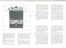
Danach wird der Steuersender wieder
mit der Abschirmhaube versehen. Ein
evtl. Einfluß der Abschirmung kann
durch Nachgleichen von L,D beseitigt
werden.
Abgleich des NF-Teils:
Der Hubregler P2wird voll aufgedreht,
der Schalter S, wird auf den Mikrofon-
eingang geschaltet. Diesem Eingang
wird vom NF-Generator eine Spannung
von 100 mV/1 kHz zugeführt. Mit P,
wird dann der Spitzen hub (75 kHz bzw.
15kHz) eingestellt.
Das Meßinstrument soll nach Abschluß
der Abgleicharbeiten bei einer Batte-
riespannung von 15 V folgende Werte
anzeigen:
Stellung Batterie
90 Skalenteile
ce Stellung Frequenz
80 -90 Skalenteile
Stellung HF
80 - 100 Skalenteile
Stellung HUB
35
-50 Skalenteile
bei 0,6 mVEingangsspannung
am Mikrofoneingang
J
-
retuned. It is essential to measure now
the operating frequency of the trans-
mitter because it may happen that the
IF deviates from its nominal value. The
nominal operating frequency will be
reached by readjusting coil L'D. Ll1,
L12,L13must be also retuned to maxi-
mum. Thereafter, the frequency of both
channels should be correct within a
tolerance of 1 kHz.
A slight frequency shift after fitting of
the screening can be compensated by
readjusting of L'D.
Alignment of the AF section:
Turn the deviation control P2 fully
clockwise and set switch S2 to micro-
phone input. Connect a signal of
100 mV/1kHz to the microphone input.
Adjust p, such that the peak deviation
(15 kHz resp. 75 kHz) is achieved.
After conclusion of the whole align-
ment procedure the control instrument
should read as follows (battery voltage
15 V):
Position BATT (battery)
90 scale divisions
Position FREQ (frequency)
80 -90 scale divisions
Position HF (high frequency)
80 - 100scale divisions
Position HUB (frequency deviation)
35 - 50scale divisions
at 0.6 mVat the microphone input
15