


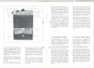

4. Anwendung
Der Sender SER 1 gestattet in Verbin-
dung mit einem hochwertigen Empfän-
ger, z. B. unserer Type ER 3, den Auf-
bau einer drahtlosen Obertragungs-
einrichtung für mittlere Reichweiten.
Die Reichweite ist abhängig vom An-
tennenaufwand der Empfangs- und
Sendestation und beträgt im ebenen
Gelände bei Benutzung von
Tragriemenantenne am Sender und
)j4-Stabantenne am Empfänger in
1,5 m Höhe ca. 1 km,
)J4-Stabantenne am Sender und Emp-
fänger (Antennen höhe je 1,5 m)
ca. 1,5 km,
Tragriemenantenne am Sender und
)J2-Dipol am Empfänger in 3 m Höhe
ca.2 km,
)J4-Stabantenne am Sender und
)j2-Dipol am Empfänger in 3 m Höhe
ca. 3 km,
)./4-Stabantenne am Sender und
)J2-Dipol am Empfänger in 10m Höhe
ca.6 km,
)j2-Dipol (3 m Höhe) am Sender (orts-
fester Betrieb) und )J2-Dipol (10 m
Höhe) am Empfänger ca. 20 km.
Das Gerät läßt sich somit als verstärk-
tes drahtloses Mikrofon für Außenüber-
tragungen bei Rundfunk- und Fernseh-
anstalten einsetzen. Die Obertragungs..
qualität entspricht Studio-Ansprüchen.
Mit mehreren Sendern lassen sich
Relaisstrecken aufbauen, wobei zweck-
mäßig stärker bündelnde Antennen
verwendet werden, weil die Relais-
stationen ortsfest sind. Für den Bedarf
der deutschen Rundfunkanstalten sind
2 Frequenzen im 4-m-Band vorgesehen.
Außerdem ist für Fernsteuer- und Fern-
wirkzwecke eine Tonmodulation über
den Leitungseingang möglich.
Dieser Eingang steht auch für draht-
lose Datenübertragung zur Verfügung,
wenn die Daten so aufbereitet sind,
daß sie in den Obertragungsbereich
des Senders passen.
Es ist natürlich auch möglich, den Sen-
der ortsfest oder im Kraftfahrzeug zu
6
4. Application
The transmitter SER 1 in conjunction
with a high quality receiver (e. g. Senn-
heiser receiver ER 3) allows the set up
of a wireless transmission system to
cover medium distances. The usable
range depends on the antenna systems
employed with the transmitter and the
receiver. The following distances can
be achieved over flat ground:
Approx. 1 km using the shoulder strap
antenna at the transmitter and a )J4
rod antenna at 1.5 m above ground at
the receiver.
Approx. 1.5 km using )J4 antennae a1C'"
1.5 m above ground at transmitter and
receiver.
Approx. 2 km using the shoulder strap
antenna at the transmitter and a )J2
dipole at 3 m above ground at the re-
ceiver.
Approx. 3 km using a i.l4 rod antenna
at the transmitter and a )j2 dipole at
3 m above ground at the receiver.
Approx. 6 km using a i.l4 rod antenna
at the transmitter and a )j2 dipole at
10 m above ground at the receiver.
Approx. 20 km using a )J2 dipole (3 m
above ground) at the transmitter (sta-
tionary operation) and a )j2. dipole
(10 m above ground) at the receiver.
Consequently the transmitter can be
used as an intensified wireless micro-
phone for location work of radio and
TV broadcasting stations. The trans-
mission quality meets broadcast stand-
ards.
0
It is also possible to build up relay ,
stations. Directional antennas could
then be used to good advantage as
relay transmitters are installed station-
ery. Two frequencies in the 4 m band
are provided for the needs of the Ger-
man broadcasting stations.
For remote-control and remote-acting
purposes a tone modulation is possible
by means of the line input. This input
serves also for wireless data transfer
in case the datas are prepared to fit
into the transmission range of the
transmitter.
The transmitter may be operated sta-
tionary or in a motor vehicle as weil
I
betreiben und eine größere Anzahl von
Empfängern anzusprechen, wie es bei
Bautrupps, Polizeieinsätzen, Führungs-
anlagen usw. erforderlich ist.
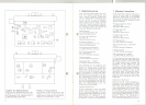
5. Bedienung
Vor dem Einschalten werden die Ton-
frequenzquellen (Mikrofon oder Modu-
lationsleitung, Datenumsetzer oder
ti"""-,Ruftongenerator) und die gewünschte
'\.,..1Antenne an die zugehörigen Buchsen
angeschlossen. Die Beschaltung der
Buchsen geht aus dem Schaltbild her-
vor. Der Eingangsumschalter wird auf
den gewünschten Eingang geschaltet.
Durch Rechtsdrehen des Wahlschalters
wird der Sender eingeschaltet. Das
Meßinstrument zeigt die Spannung der
Batterie an, der Zeiger soll sich im
roten Feld befinden. Beim Weiterdre-
hen des Schalters (Stellung FREO)
zeigt das Instrument an, ob die Ouarz-
kontrolle des Steuersenders funktio-
niert (elektronische Rastung). Auch hier
soll sich der Zeiger im roten Feld be-
finden.
In der Stellung HF wird die Hochfre-
quenzspannung des Senders an der
Antennenbuchse angezeigt. Falls gut
angepaßte 60-Q-Antennen oder auch
ein Meßabschluß benutzt werden, läßt
sich nun mit dem Instrument die HF-
Leistung kontrollieren - Zeiger im ro-
ten Feld. Falls die Antenne Blindkom-
O
ponente aufweist, ist die Anzeige nicht
voll gültig. Fehlanpassungen verringern
die Reichweite des Senders, schaden
diesem jedoch nicht.
In der Stellung HUB des Umschalters
wird die Modulation des Senders über-
wacht. Bis zu einer Anzeige von 40
Skalenteilen arbeitet der NF-Teil mit
linearer Amplitudencharakteristik. Dar-
über hinausgehende Amplituden wer-
den entsprechend der Funktion des
Begrenzerverstärkers klirrarm herab-
gesetzt, um eine Obermodulation des
Senders
zu vermeiden. Wenn der Zei-
ger in den roten Bereich kommt, ist
die Obersteuerungsgrenze erreicht und
es muß mit Verzerrungen gerechnet
to address a larger number of receiv-
ers as it is necessary for different
applications e. g. guiding installations,
construction team.
5. Operation
Before the transmitter is switched on
the audio-frequency signal source (e. g.
microphone, modulation line or data
converter) and the desired antenna
should be connected to the corre-
sponding sockets. The wiring of the
sockets can be seen from the circuit
diagram. The input change-over switch
must be set to the type of input re-
quired.
The transmitter is switched on by turn-
ing the selector switch clockwise to
position "BA TT". The instrument indi-
cates now the battery voltage and the
pointer must rest in the red field. With
the switch turned to position "FREO"
the instrument shows whether the crys-
tal control of the transmitter works
(electronic frequency lock-in). In this
case the pointer should be in the red
field as weil.
In position "HF" the radio frequency
voltage at the antenna socket of the
transmitter is indicated. Using a weil
matched 60 Q antenna or a dummy an-
tenna the instrument facilitates check-
ing of the RF power (pointer in the red
section). The indication is not really
valid if the antenna shows reactive
components. Mismatching will reduce
the usable distance of the transmitter
but nothing can be damaged.
With the selector switch in position
"HUB" the modulation of the trans-
mitter is controlled. The amplitude
characteristic of the AF part is linear
up to an indication of 40 divisions on
the scale. Amplitudes exceeding this
value will be reduced nearly distortion-
free according to the function of the
limiter stage to prevent overmodulation
of the transmitter. When the pointer
moves into the red field the limit is
reached where distortiol1 will occur.
The AF signal connected to the trans-
7