


- - -
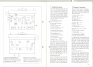
6. Schaltungsbeschreibung
Der Sender SER 1 ist ein 1 W-FM-
Sender, der durch ein Mikrofon oder
über eine 200-Q-Leitung moduliert wer-
den kann. Der Sender ist für Sprech-
funk mit 15 kHz Hub und Reportage-
zwecke mit 75 kHz Hub geeignet.
Die Eingänge für Mikrofon (Bu 1) und
für Leitung (Bu 2) werden über Wahl-
schalter (S 1) jeweils mit dem Eingang
des NF-Verstärkers verbunden. Der
eigentliche NF-Verstärker besteht aus
den Transistoren T" T2, T3. Am Aus-
gang von T3 ist ein Diodenklipper (04,
05) eingeschaltet. In Verbindung mit
dem Einsteller P, wird die NF-Modu-
lationsspannung begrenzt und entspre-
chend dem max. zulässigen Hub ein-
gestellt.
Die Anordnung von Transistor T4 und
der Diodenschaltung 07, 08 gewinnt
eine Gleichspannung, die der Aus-
gangswechselspannung proportional
ist. Diese Gleichspannung wird zur
Regelung benutzt. Geregelt wird der
differentielle Widerstand von zwei anti-
parallel geschalteten Dioden (02, 03),
die die Gegenkopplung von T, auf T,
beeinflussen. Die erforderliche Sym-
metrie der Regelspannung wird mit
dem Transistor T5 und der Zenerdiode
09 erreicht.
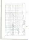
Mit der Diode 06 wird eine Gleichspan-
nung zur Aussteuerungskontrolle ge-
wonnen. Das Potentiometer p, regelt
die Eingangsempfindlichkeit. Der Re-
gelbereich des Verstärkers wird mit
kleiner werdender Empfindlichkeit
ebenfalls kleiner (s. Abb. S. 16).
Die Modulation wird dem Oszillator T6
zugeführt und bewirkt durch Änderung
des Emitterstromes eine lineare FM.
Die Frequenz des Oszillators liegt bei
der halben Sendefrequenz. Der Schal-
ter S, bewirkt eine Änderung der Fre-
quenz für den zweiten Kanal. Die Fre-
quenz wird anschließend im T7 verdop-
pelt und zwei Trennstufen TB und T17
zugeführt. Die Trennstufe T17 gibt die
Frequenz an die Frequenzstabilisie-
rungsschaltung weiter. Diese enthält
einen Ouarzoszillator T19, dessen Fre-
quenz durch Umschalten der Ouarze
0" 0, geändert wird. Diese Ouarzfre-
quenz wird verdoppelt in T'B und dann
einem Mischer 017 - 020 zugeleitet. Der
10
6. Circuit Description
The transmitter SER 1 is a frequency
modulated transmitter with a RF power
of 1 W. It can be modulated by means
of a microphone or through a 200 Q
line. The transmitter is intended for
radiotelephony with a deviation of
15 kHz or for reporting purposes with
75 kHz deviation.
The microphone input (Bu 1) or the
line input (Bu 2) are connected to the
amplifier via the selector switch (S 1).
The AF amplifier consists of the tran-
sistors T" T2, T3. The output of T3 is
connected to a diode limiter (04, D5).
(
~
In conjunction with the potentiometer
P, the AF modulating voltage will be
limited and set to the value required
for the maximal permissible deviation.
A circuit consisting of transistor T4 and
the two diodes 07, OB produces a dc
voltage proportional to the AF output
voltage. This dc voltage is used as a
control voltage for regulating of the
differential resistance of two antiparal-
lel connected diodes (0" 03). These
diodes affect the negative feedback
from T2 to TL The necessary balance
of the control voltage is achieved by
means of transistor T5 and the zener
diode 09.
Diode 06 produces a dc voltage for
indication of the modulation. Potentio-
meter P2 controls the input sensitivity.
With decreasing sensitivity of the
amplifier according to the setting of p,
the range of the automatic gain control
decreases too (see figure on page 16).
The modulating voltage is fed to the
0
,
oscillator T6 and causes a linear fre- '
quency modulation by changing the
emitter current. The oscillator fre-
quency is half of the carrier frequency.
The switch S, changes the frequency
to obtain the second carrier frequency.
The oscillator frequency is doubled by
means of T7 and connected to two
separator stages TBand T17.The sepa-
rator stage T17passes the signal on to
the frequency stabilizing circuit. This
circuit contains a crystal-controlled
oscillator T,9. Its frequency can be
alte red by switching over of the crystals
0, and 0,. The crystal frequency is
doubled by T'B and led to the mixer
stage 017 - 020.At the same time the
Mischer erhält außerdem über T17 die
Frequenz des freilaufenden Oszillators
T6. Die Differenz beider Frequenzen
bildet eine Zwischenfrequenz, die 3-
stufig verstärkt wird T'4, T,5, Ti6.
Der folgende Diskriminator bildet dar-
aus eine verstimmungsabhängige Re-
gelspannung, die in den kompensier-
ten Gleichspannungsverstärkern T12,TB
noch einmal verstärkt wird. Danach
wird die Gleichspannung der Basis von
T6 zugeführt. Die Stabilität des Steuer-
senders ist bedingt durch die Eigen-
schaften des Ouarzosziilators, des Dis-
11'" kriminators und der Stabilität des frei-
""-- laufenden, modulierten Oszillators, di-
vidiert durch die Nachstimmgüte der
Regelschaltung. Aus allen Faktoren er-
gibt sich eine Stabilität von :t 3 .10-5.
Hinter der letzten ZF-Stufe T'4 wird mit
einer Gleichrichterschaltung 0,6 eine
Spannung abgenommen und dem Meß-
instrument zugeführt. Mit dem Vorhan-
densein dieser Spannung wird die ZF-
Bildung und damit die richtige elek-
trische Rastung des freilaufenden Os-
zillators angezeigt.
An die Trennstufe TB schließt sich der
HF-Leistungsverstärker an. Mit den
Stufen T9, T,0, T11wird die Leistung auf
1 W aurgestockt. Der letzten Stufe folgt
ein Filter zur Anpassung und Ober-
wellensiebung. Die HF-Spannung an
der Antennenbuchse ist bei Abschluß
mit 60 Q ein Maß für die Ausgangs-
leistung des Senders. Die mit der
Diode 011 gleichgerichtete Spannung
wird bei entsprechender Stellung des
Schalters S3 vom eingebauten Meßin-
strument angezeigt.
«,
mixer receives via T17the signal of the
free-running oscillator T6. The diHer-
ence or the two frequencies is used
as an intermediate frequency which is
ampliried by T16,T'5, T14.
The following discriminator changes
the IF signal into a control voltage
which depends on the frequency shift
or the free-running oscillator. The con-
trol voltage is increased by compen-
sated dc amplifiers (T12, T13) and then
connected to the base of T6. The fre-
quency stability of the transmitter is
dependent on the characteristics or the
crystal-controlled oscillator, the dis-
criminator and the stability of the free-
running, modulated oscillator in eon-
nection with the quality of the control
circuit. The resulting frequency sta-
bility comes to :t 3. 10-5. From the last
IF stage T'4 a voltage is taken off,
rectified by diode 0,6 and red to the
measuring instrument. The presence of
this voltage indicates that the IF signal
is produced and, hence, the working of
the electronic frequency lock-in of the
free-running oseillator.
The RF power amplifier is iinked to the
output of the separator stage T8. With
T9, TlO, T11 an output power of 1 VVis
achieved. A filter following the last
amplifier stage serves for attenuation
of harmonics and for matching pur-
poses. The RF voltage at the antenna
socket is a measure for the output
power of the transmitter in the case
that the output has a termination of
60 Q. The voltage rectified by 011 is
indicated in position HF of the seleetor
switch.
11