Product overview
7
Overview of the displays
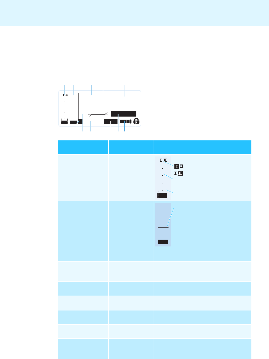
After switch-on, the receiver displays the “Receiver Parameters” standard display. For further
illustrations and examples of the different standard displays, please refer to page 16.
This standard display displays the operating states of the receiver and provides the most
important information on the received transmitter – provided the transmitter supports this
function.
Display
Transmitter/
Receiver
Meaning
ቢ RF level “RF”
(Radio Frequency)
Receiver
ባ Audio level “AF”
(Audio Frequency,
see page 25)
Transmitter
ቤ Frequency bank
and channel
(see page 24)
Receiver Current frequency bank and channel number
ብ Frequency
(see page 24)
Receiver Current receiving frequency
ቦ Name
(see page 24)
Receiver Freely selectable name of the receiver
ቧ Pilot tone “P”
(see page 27)
Receiver Activated pilot tone evaluation
ቨ Equalizer setting
(see page 25)
Receiver Current equalizer setting
ቩ Output gain
(see page 25)
Receiver Current output gain of the audio signal
available at the ¼” (6.3 mm) jack socket ¸ /
XLR-3M socket ¹
543.200
B.Ch: 20.64
PEAK
MUTE
EQ:
+ 12dB
-10
040
30
20
10
-20
-30
-40
AF
RF
MHz
**2000**
SKM2000
P
ብቦ
ቧቨ ቩ ቪ ቫቭ ቮ
ቢባ ቤ
40
30
20
10
RF
D
i
vers
i
ty
di
sp
l
ay:
Antenna input I is active
Antenna input II is active
RF signal level:
Field strength of the received signal
Squelch threshold level
PEAK
-10
0
-20
-30
-40
AF
Mo
d
u
l
at
i
on o
f
t
h
e transm
i
tter
with peak hold function
When the display shows full
deflection, the audio input level is
excessively high. When the trans-
mitter is overmodulated frequently
or for extended periods of time, the
“PEAK” display is shown inverted.


