


Putting the devices into operation
13
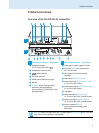
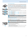
Daisy chaining audio signals
You can transmit the same audio signal (e.g. the sum of all audio signals) to several diversity
receivers of a multi-channel system. To do so, you have to daisy chain this audio signal from
one transmitter to the next via the output sockets LOOP OUT BAL L(I) ¹ or
LOOP OUT BAL R(II) Ƹ. The audio signal is then transmitted by all transmitters on one of the
two audio channels L(I) or R(II). The second audio channel allows you to transmit an
individual audio signal (e.g. the instrument of a musician). Using the balance setting on the
receiver, you can then adjust the relative levels of the sum of all audio signals and the
individual audio signal. For this, the transmitter has to be set to stereo mode and the receiver
to Focus mode.
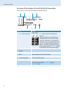
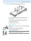
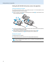
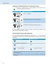
To daisy chain an audio signal from one transmitter to the next:
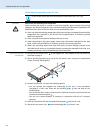
̈ Route a signal from the mixing console to the input socket (in this example:
BAL AF IN R(II) ƻ) of transmitter A.
̈ Connect the output socket LOOP OUT BAL R(II) Ƹ of transmitter A to the input socket
BAL AF IN R(II) ƻ of transmitter B.
̈ Connect the output socket LOOP OUT BAL R(II) Ƹ of transmitter B to the input socket
BAL AF IN R(II) ƻ of transmitter C.
̈ Repeat for the other transmitters.
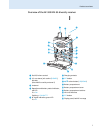
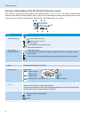
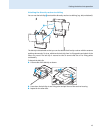
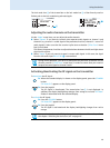
Connecting transmitters in a network
You can connect several transmitters in a network. The transmitters are remote controlled via
a PC running the “Wireless Systems Manager” (WSM) software. This software will assist in
the quick and safe configuration of multi-channel systems.
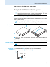
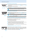
̈ Connect a standard network cable (at least Cat 5) to the LAN socket ¸ of the transmitter.
̈ Connect your transmitter to an Ethernet switch.
̈ Connect the other transmitters to the Ethernet switch.
̈ Connect a PC to the Ethernet switch.
When a transmitter is properly connected to the Ethernet switch or the PC, the yellow
LED µ at the rear of the transmitter lights up.
For further information on network operation using the WSM software, refer to page 27.
L(I)
R(II)
+22dBu
MAX
Loop Out
BAL
L(I)
R(II)
BAL
AF IN
+22dBu MAX
RF OUT
L(I)
R(II)
+22dBu
MAX
Loop Out
BAL
L(I)
R(II)
BAL
AF IN
+22dBu MAX
RF OUT
L(I)
R(II)
+22dBu
MAX
Loop Out
BAL
L(I)
R(II)
BAL
AF IN
+22dBu MAX
RF OUT
A
B
C
The AF output sockets LOOP OUT BAL L(I) ¹ and/or LOOP OUT BAL R(II) Ƹ will work
only when the transmitter is switched on and powered (see page 12).
The “Wireless Systems Manager” (WSM) software can be downloaded from the
corresponding product page on our website at www.sennheiser.com.
L(I)
+22dBu
MAX
Loop O
BAL
0682
FREQ Range-D 780-822 MHz
DESIGNED AND MADE IN GERMANY FMO
Stereo Transmitter SR 3
IDENT NO 627925
SER NO 2518100155
IC 2099A-G3SREK
¸µ