


9
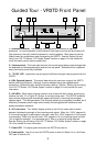
Guided Tour - VT3L / VT3
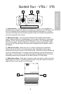
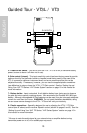
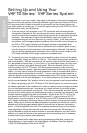
1: Input connector - The input device is connected here. The VT3L is supplied with
either a lavalier or headset microphone (connected via a Switchcraft mini-XLR jack), while
the VT3 is supplied with a permanently connected cable that terminates at a 1/4" plug.
A wiring chart showing the connections to popular lavalier and headset microphones can
be found on page 49 of this manual.
2: Battery level meter - This set of three multicolor LEDs indicates relative battery
power, indicating whether the installed battery is at low (red), mid (yellow) or high (green)
strength. One or more of these will light whenever the VT3L or VT3 is powered on (see
#5 on the next page). When all three are lit, the battery is at maximum strength. When
only the red “low” indicator lights, RF performance is degraded and the battery needs to
be replaced.
3: Audio on-off switch - When set to the “on” position, audio signal is transmitted.
When set to the “off” position, the audio signal is muted. Because the carrier signal
remains during muting, no “pop” or “thud” will be heard. Note that turning this off does
not
turn off the transmitter power—it is simply a way to temporarily mute the transmission of
audio signal. If you don’t plan on using the transmitter for extended periods, turn off the
transmitter power by using the power on-off switch (see #5 on the next page).
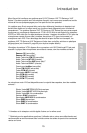
4: Battery door release - Press gently inwards on these two indents in order to open the
battery door of the VT3L or VT3 and access the Power on-off switch (see #5 on the next
page) and Gain control (see #6 on the next page).
AUDIO
▲
ON
BATTERY
LOW MID HIGH
1
2
3
SAMSON
ENGLISH
INPUT
SAMSON
VHF BELTPACK TRANSMITTER
4
4
VT3