


5
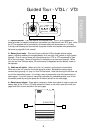
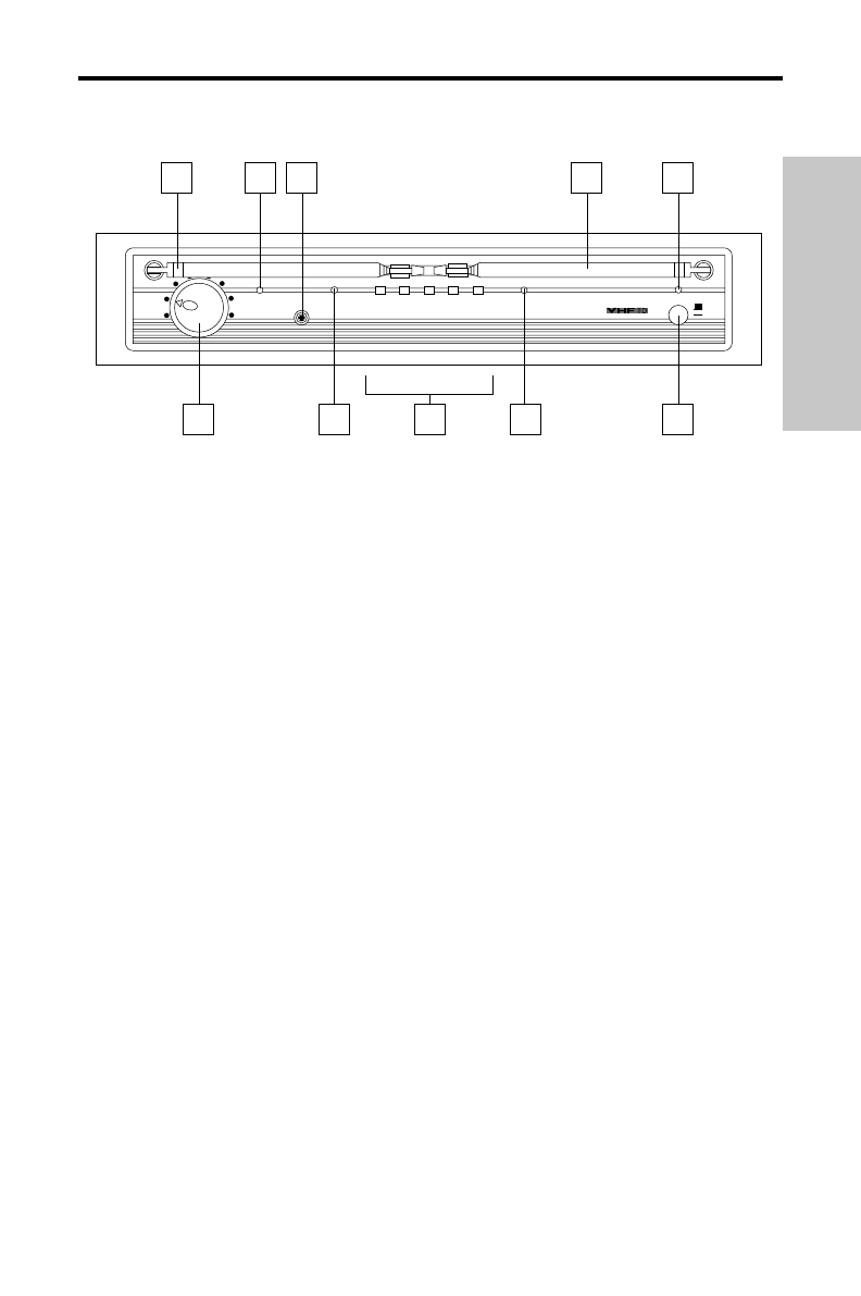
Guided Tour - VR3TD Front Panel
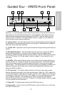
1: Antennas (A and B) - The antenna mountings allow full rotation for optimum
placement. In normal operation, both Antenna A (the antenna on the left) and Antenna B
(the antenna on the right) should be placed in a vertical position. Both antennas can be
folded inward for convenience when transporting the VR3TD. See the “Setting Up and
Using Your VHF TD Series / VHF Series System” section on page 10 in this manual for
more information about antenna positioning.
2: Volume control - This knob sets the level of the audio signal being output through both
the balanced and unbalanced output jacks on the rear panel. Reference level is obtained
when the knob is turned fully clockwise.
3: “TX ON” LED - Lights when carrier signal of sufficient strength is being received by the
VR3TD.
4: SQL (Squelch) control - This control determines the maximum range of the VR3TD
before audio signal dropout. Although it can be adjusted using the supplied plastic
screwdriver, it should normally be left at its factory setting. See the “Setting Up and Using
Your VHF TD Series / VHF Series System” section on page 10 in this manual for more
information.
5: A/B LEDs - When signal is being received, one of these will be lit yellow, showing you
whether the (left) “A” or (right) “B” receiver is currently being used. The VR3TD constantly
scans its two antennas and automatically selects whichever is receiving the strongest,
clearest signal. This
Microprocessor True Diversity switching is completely inaudible, but it
effectively increases overall range while virtually eliminating potential interference and
phase cancellation problems.
6: AF Level meter - This “ladder” display (similar to the VU bar meter used on audio
devices) indicates the strength of the incoming audio signal. When the “100%” segment is
lit, the incoming signal is optimized at unity gain; when the “125%” segment is lit, the signal
is overloading. When only the left-most “10%” segment is lit, the incoming signal is at just
10% of optimum strength. If no segments are lit, little or no signal is being received.
See the “Setting Up and Using Your VHF TD Series / VHF Series System” section on page
10 in this manual for more information.
7: Power LED - This lights green whenever the VR3TD is turned on.
8: Power switch - Use this to turn the VR3TD power on and off. When it is on, the Power
LED (see #7 above) is lit.
10% 25% 75% 100%
125%
MAX.
VR3TD VHF TRUE DIVERSITY RECEIVER
TX
VOLUME
SQL. MIN.
POWER
OFF
ON
SAMSON
ANT. A
ANT. B
1
2
3 4
6
5
5
1 7
8
Series
ENGLISH