


ENGLISH
4
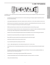
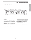
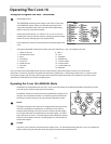
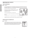
C com 16 Front Panel Layout
1 PROGRAM LED’S 1- 8
– When illuminated, indi-
cates the associated Program (1-SMOOTH VOCAL,
2-AGGRESSIVE VOCAL, 3-BASS, 4-SLAP BASS, 5-
ACOUSTIC, 6-FUNK GUITAR, 7-SUSTAIN, 8-PERC 1) is
selected.
2
PROGRAM LED’S 9-16
– When illuminated, indi-
cates the associated Program (9-PERC 2, 10-SOFT,
11-DYNAMIC, 12-ENHANCED, 13-STEREO COMP,
14–STEREO LIMIT,15-STEREO MASTER,16-MANUAL) is
selected.
3 PROGRAM SELECTOR
– Rotary encoder control
knob used to select the 16 Programs.
4 GAIN REDUCTION METER
- Displays the amount of
Gain Reduction when Compressor circuit is activated.
5 SENSITIVITY
- Used to set the minimum signal level
at which the Compressor circuit begins to function
.
6 RATIO
- Controls the amount of Gain Reduction in
proportion to the amount of signal over the selected
threshold level.
7 RELEASE
- Selects the amount of time the com-
presssor takes to return the signal to the orignal
level.
8 OUTPUT
- Used to set the final level after the com-
pression circuit is applied.
9 INPUT/OUTPUT METER
- Six segment LED meter
displays the Input or Output signal level based on
the settings of the I/O meter switch.
10 MAINS POWER SWITCH
-
When switched on, the
green LED will light, indicating the C com 16 is
powered on and ready for operation.
11 ENHANCER
- Activates the C com 16’s Enhancer cir-
cuit which restores the high end loss resulting from
extreme Gain Reduction.
12 ATTACK
- Adjusts the amount of time the compres-
sor takes to reach full gain reduction .
13 BYPASS
- Used to switch the C com 16’s compression
circuit on and off. The C com 16 is engaged when
the BYPASS LED lights green.
14
INPUT/ OUTPUT METER SELECT SWITCH
14 INPUT/ OUTPUT METER SELECT SWITCH14
- Selects
either Input or Output level to be displayed on the
Input/Output Meter.
C com 16 Front Panel Layout