ENGLISH
8
Operating The C com 16
Connecting the C com 16
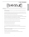
The C com 16 can be easily connected to most any audio device thanks to the use of standard 1/4-inch phone
connectors, and to the +4/-10 switch input level switch. You can use your C com 16 in a mixers insert point, or
in-line between your instrument or other line level audio device. Once you decide what signal you will be con-
necting to your C com 16, you can choose your wiring and level setting. To do this, follow the sections below. For
a detailed wiring diagram, see page 17 of this manual.
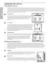
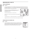
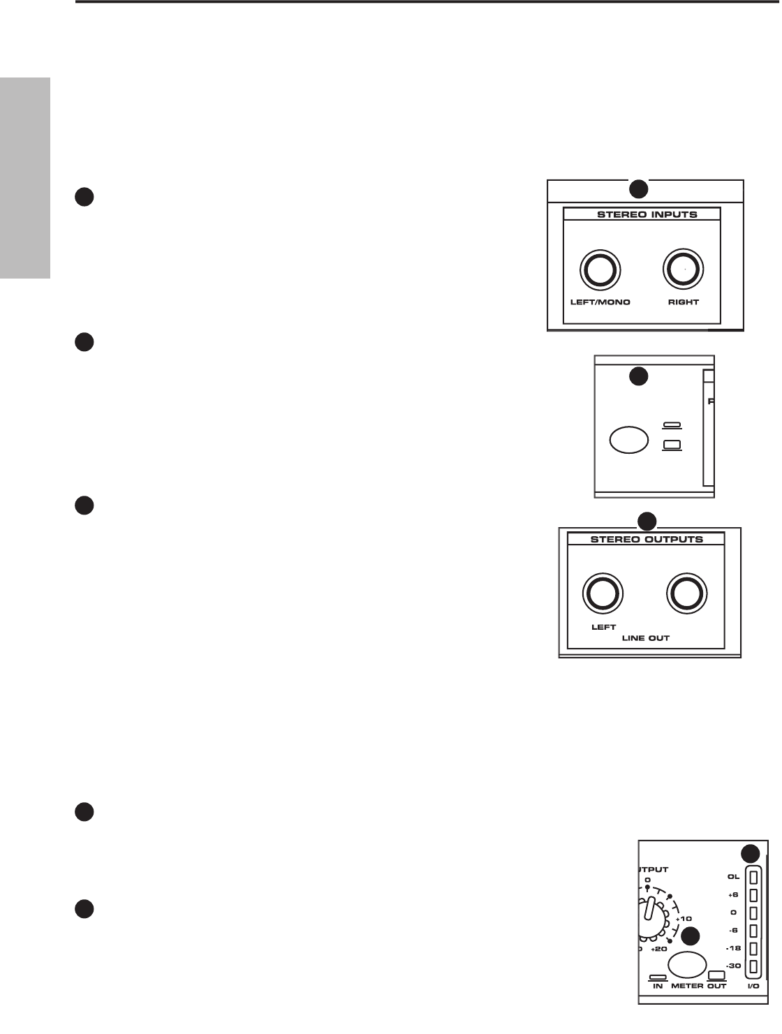
STEREO INPUTS
The rear panel STEREO INPUTS use 1/4-inch connectors for the line level
inputs. A mono signal can be inserted into the LEFT/MONO Input, and
that signal will be split and sent the RIGHT input so that the STEREO
OUTPUTS will have the same signal on both the LEFT and RIGHT
OUTPUTS.
+4/-10 Switch
The +4/-10 switch located on the rear panel is used to adjust the C com 16’s
input to the best operating level for the device that you are connecting. Press
the +4/-10 switch to the -10 position when connecting signals from instru-
ments like guitars and bass guitars, or for consumer audio devices like CD,
MD and Cassette player/recorders. Press the +4/-10 switch to the +4 posi-
tion when connecting to the insert-point of a mixer, or to pro audio gear like
effects processors and recorders.
STEREO OUTPUTS
On the C com 16’s rear panel you will find the STEREO OUTPUTS which
are 1/4-inch TRS (TIP/RING/SLEEVE) connectors carrying the balanced
line level outputs. If a mono signal is inserted into the LEFT/MONO
Input, that signal will be split and sent the RIGHT input so that the
STEREO OUTPUTS will have the same signal on both the LEFT and
RIGHT OUTPUTS.
Setting Input and Output Levels
The C com 16 is capable of handing a variety of input signals ranging from low level guitar/instrument sig-
nals, through -10dBV line level signals from consumer audio gear, all the way up to +4dBu signals from pro
audio devices. Whether you are using one of the C com 16’s powerful internal pre-set PROGRAMS or using the
MANUAL mode to dial up your own sound, it’s important to set a good input and output level in order to main-
tain the best quality signal. The following section details the various controls and meters used to set a good
input and output level.
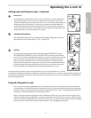
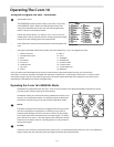
I/O METER
The I/O meter is a six segment LED display which can be set to show the INPUT or
OUTPUT level, depending on the position of the METER switch. The I/O meter dis-
plays the level in a dB scale from OL (OVERLOAD), +6, 0, -6, -18 and -30.
METER Switch
The METER switch is used to assign either the INPUT or OUTPUT signal to the I/O
meter. Press the switch to the OUT position to monitor the C com 16’s OUTPUT level.
Since you will adjust the input level first, place the METER switch to the IN position.
RIGHT
+4
-10
RIGHT
+4
-10
RIGHT
+4
-10
1
1
2
2
3
3
4
4
5
5


