


8
Names of Things and What They Do
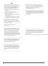
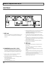
Control Panel
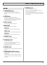
fig.01-01
1. INPUT SELECT Button
Use this button to select MIC or LINE input.
This switches the input to match the connected device
(mic or line-level device).
The MIC indicator lights when MIC is selected; when
LINE is selected, the LINE indicator lights.
2.
VOICE ENHANCER Button (CH 1, CH 2)
This switches the Voice Enhancer effect on and off when
the input is set to MIC.
Switching this on enables you to give the sound a clearer
contour and make vocals more prominent.
3. REVERB/DELAY Knob (CH 1, CH 2)
You can switch between reverb and delay by adjusting
the knob position.
When not using reverb or delay, set the knob to “OFF.”
The reverb and delay position on the scale shown on the
panel is approximate. Listen to confirm the effect as you
adjust the amount of effect applied.
4. REVERB Knob (CH 3, CH 4)
This adjusts the amount of reverb.
When not using reverb, set the knob to “OFF.”
5. VOLUME Knobs
These adjust the volume levels of the channels.
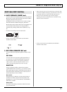
* To minimize noise as much as possible, we recommend
turning the VOLUME knob for any channel not being used to
0 and setting INPUT SELECT to LINE.
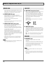
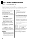
6. ANTI-FEEDBACK (CH 1, CH 2)
This automatically detects and eliminates acoustic
feedback.
For further instructions on how to use anti-feedback,
refer to “About the Anti-Feedback Function” (p. 16)
ON/OFF Button
Press this button to turn the function on.
When switched on, the indicator lights, and the system
automatically works to prevent sudden feedback, as well
as feedback that occurs during quiet stretches.
SWEEP Button
When the ON/OFF button is set to ON, holding down
this button for one second or longer generates a
calibration signal from the speakers. The microphone
picks up the sound and the SA-300 analyzes the
characteristics of the microphone and the surroundings.
Based on the results of this analysis, the microphone and
environmental characteristics are compensated for
automatically, making it difficult for feedback to crop
up.
The indicator flashes while this automatic correction is in
progress. When the process is completed, the indicator
remains lit, signifying that the feedback prevention
function is in effect.
1 2
14
7 8 9
3
5
4
1011 12 13
6
15
Channel Controls (CH 1–4)