


8
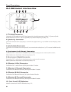
GLC-SB Student Interface Box
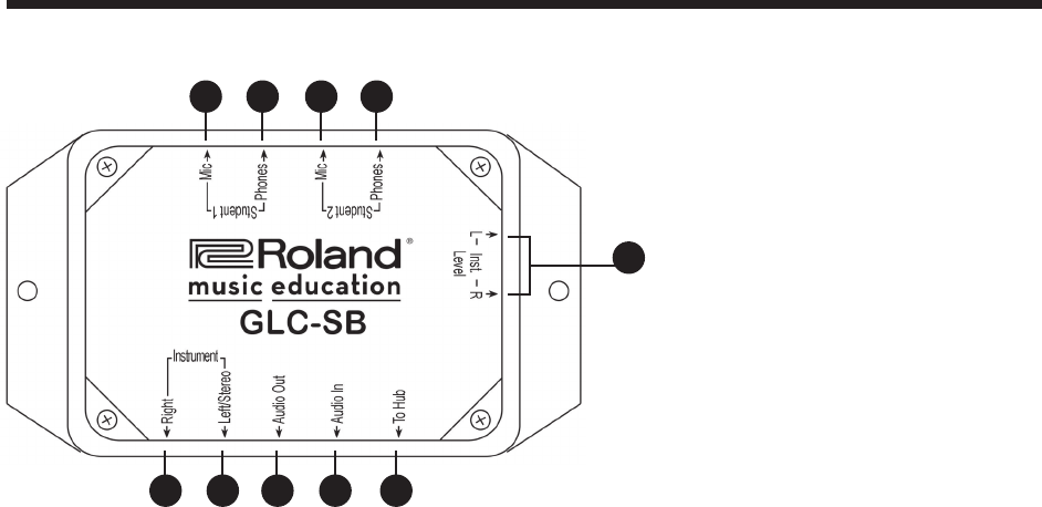
Panel Descriptions
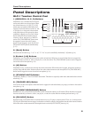
1. [To Hub] Connector
Connects the GLC-SB interface box to the [Teacher] connector (for the teacher’s instrument) or a Student [1–8] connector (for the
student instruments) on the GLC-1 Hub via a supplied RJ-45 (8-conductor telephone-type) cable (p. 10).
2. [Audio In] Connector
Connects the interface box to the output jack(s) on an external audio playback device (e.g. CD, handheld recorder, MP3 player, Music
Tutor, etc.).
3. [Audio Out] Connector
Connects the GLC-SB interface box to the input jack(s) on an external audio recording device (e.g. CD, computer, handheld recorder,
etc.).
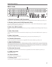
4. [Instrument Left/Stereo] Connector
Connects the GLC-1 interface box to the headphone jack or left/stereo output jack on a student/teacher instrument.
Note: In Split mode, this is Student 1’s [Instrument] input (p. 10).
5. [Instrument Right] Connector
Connects the GLC-1 interface box to the right output jack on a student/teacher instrument.
Note: In Split mode, this is Student 2’s [Instrument] input (p. 10).
6. [Student 1 Mic] Connector
Connects the GLC-1 interface box to the [Mic] jack on Student 1’s headset.
7. [Student 1 Phones] Connector
Connects the GLC-SB interface box to the [Phones] jack on Student 1’s headset.
8. [Student 2 Mic] Connector
Connects the GLC-SB interface box to the [Mic] jack on Student 2’s headset.
9. [Student 2 Phones] Connector
Connects the GLC-SB interface box to the [Phones] jack on Student 2’s headset.
10. [Inst. Level L/R] Adjusters
Adjust the volume level of the GLC-SB interface box (p. 12).
5 4 3 2 1
6 7 8 9
10