


7
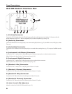
Panel Descriptions
GLC-1 Hub
1 2 3 4 5 6 7 8
9 10 11 12 13 14 15 16
17 18 19 20 21 22 23 24
25 26 27 28 29 30 31 32
41 42 43 44 45 46 47 48
33 34 35 36 37 38 39 40
Aux.
In
CD
In
Rec.
Out
Mon.
Out
Teacher Split
On/Off
Remote USB On/OffPower
9vAC
Right
Left
2
1 43 5 6 7 8 9 10 11
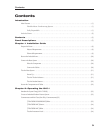
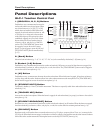
1. Student Instrument [1–8] Connectors
Connect the GLC-1 Hub to the student GLC-SB interface boxes via supplied RJ-45 (8-conductor telephone-type) cables (p. 10).
2. Student Instrument [9–48] Expansion Slots
Accept GLC-EXPKIT (8-student) expansion boards to connect the GLC-1 Hub to all GLC-SB interface boxes via supplied
RJ-45 (8-conductor telephone-type) cables (p. 1 ).
3. [Aux. In] / [CD In] Jacks
Connect to the output jacks of external audio playback devices (e.g. CD players, handheld recorders, MP3 players, Music Tutors, etc.)
(p. 16).
4. [Rec. Out] Jacks
Connect the hub to the input jacks of an external audio recording device (e.g. CD recorder, handheld recorder, computer, etc.)
(p. 16).
5. [Mon. Out] Jacks
Connect to the input jacks on an external monitoring system (e.g. stereo power-amp with speakers) (p. 17).
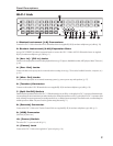
6. [Teacher] Connector
Connects to the teacher’s GLC-SB interface box via a supplied RJ-45 (8-conductor telephone-type) cable (p. 10).
7. [Split On/Off] Switch
Determines the operational mode of the GLC-1. When this switch is set to Off (i.e. to the right), the GLC-1 operates in Standard mode,
accommodating one stereo instrument per student interface box. When this switch is set to On (i.e. to the left), the GLC-1 operates in Split
mode, allowing two mono instruments per student interface box, or a Roland piano operating in Twin Piano mode, accommodating two
students per station. Note: The power must be off when setting this switch (p. 1).
8. [Remote] Connector
Connects the GLC-1 Hub to the Teacher Control Pad via a supplied RJ-45 (8-conductor telephone-type) cable (p. 1).
9. [USB] Connector
[Reserved for future use.]
10. [Power] Switch
Turns the GLC-1 system on and off (p. 11).
11. [Power] Jack
Connects the GLC-1 Hub to the supplied AC power adapter (p. 10).