


10
Review the Included Items
The GLC-1 music conferencing system includes all of the components needed to connect up to eight student instruments and
one teacher instrument in stereo. Before setting up the GLC-1, be sure you have the following components:
Item Qty.
GLC-1 Hub . . . . . . . . . . . . . . . . . . . . . . . . . . . . . . . . . . . . . . . . . . . . . . . . . . . . . . . . . . . . . . . . . . . . . . . . . . . . . . . . . . . . . . . . . . . . . . . . . . . . .(1)
GLC-1 Teacher Control Pad . . . . . . . . . . . . . . . . . . . . . . . . . . . . . . . . . . . . . . . . . . . . . . . . . . . . . . . . . . . . . . . . . . . . . . . . . . . . . . . . . . . .(1)
GLC-SB Student Interface Box . . . . . . . . . . . . . . . . . . . . . . . . . . . . . . . . . . . . . . . . . . . . . . . . . . . . . . . . . . . . . . . . . . . . . . . . . . . . . . . . . . .(9)
Stereo Headsets . . . . . . . . . . . . . . . . . . . . . . . . . . . . . . . . . . . . . . . . . . . . . . . . . . . . . . . . . . . . . . . . . . . . . . . . . . . . . . . . . . . . . . . . . . . . . . . . . .(9)
RJ-45 (8-conductor telephone-type) Cables . . . . . . . . . . . . . . . . . . . . . . . . . . . . . . . . . . . . . . . . . . . . . . . . . . . . . . . . . . . . . . . . . . . . .(10)
1/4” to 1/4” TRS Cables . . . . . . . . . . . . . . . . . . . . . . . . . . . . . . . . . . . . . . . . . . . . . . . . . . . . . . . . . . . . . . . . . . . . . . . . . . . . . . . . . . . . . . . .(9)
AC Adapter . . . . . . . . . . . . . . . . . . . . . . . . . . . . . . . . . . . . . . . . . . . . . . . . . . . . . . . . . . . . . . . . . . . . . . . . . . . . . . . . . . . . . . . . . . . . . . . . . . . . .(1)
Connect the Basic System
Note: It’s strongly recommended that all connections be made with the power off.
Place the Components
• Place the teacher’s instrument in an optimal teaching position.
• Place student instruments in rows facing the teacher’s instrument (row configuration is optional). Be sure to allow extra
space behind each student station so that the teacher can move easily from station to station.
• Place the GLC-1 Hub in a central location.
• Place the Teacher Control Pad on or near the teacher’s instrument.
• Optional—Place the external audio playback/recording device(s) (e.g. CD player/recorder, MP3 player, handheld
recorder, computer, etc.) on or near the teacher’s instrument.
• Optional—Place the external audio monitor(s) to the side of the teacher’s instrument facing the student instruments.
• Optional—Place the video monitor(s) on a pedestal or wall mount near the teacher’s station (facing the student instruments).
A projector may also be used, but be sure to allow sufficient, unobstructed space between the projector and screen.
Connect the Cables
• Connect all devices to AC power strips as described under “Electrical Requirements.” Note: It’s strongly recommended
that all connections be made with the power off.
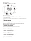
• Mount one GLC-SB interface box on each instrument (including the teacher’s instrument). This can most easily be
accomplished using double-sided adhesive pads.
• Use the supplied 1/4” to 1/4” TRS cables to connect the headphone output of each instrument to the [Instrument Left/
Stereo] input on each GLC-SB interface box.
• Optional—Numerically label each student instrument so that the teacher can easily identify student stations from the
optimal teaching position.
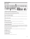
• Connect the GLC-1 Teacher Control Pad to the [Remote] connector on the GLC-1 Hub using a supplied RJ-45
(8-conductor telephone-type) cable.
• Connect the teacher’s GLC-SB interface box to the [Teacher] connector on the hub using a supplied RJ-45
(8-conductor telephone-type) cable.
Chapter 1: Installation Guide