


Rev.1.00 2003.05.08
page 10 of 23
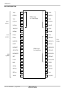
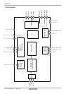
M65881AFP
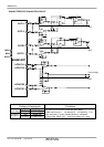
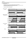
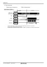
OUTL1, OUTL2, OUTR1 and OUTR2 are pulse output modulated ∆Σ output to PWM signal.
These pins are connected to external Power Driver ICs.The PWM output can be selected
PWM Output Format 1, 2, 3 and 4 by serial control data(System1 mode, bit22,23 ).
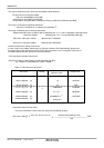
PWM Output Form1 : General Modulation
PWM Output Form2 : Symmetrical Modulation
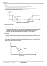
PWM Output Form3 : Modulation returned with time domain.
( The rise and fall edge of Lch and Rch in a term are reverse.)
PWM Output Form4: Modulation returned with time domain.
( The rise and fall edge of Lch and Rch in a term are same timing.)
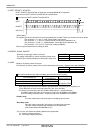
In each 4 forms, the rate and bit length of PWM Output can be changed.
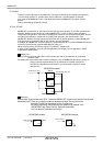
Moreover, an output mute function and an output pins reverse function
can be controlled by the pin setting or serial control.
Refer to pin setting of the following page about a phase of the PWM output
for Power Stage and Headphone.
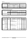
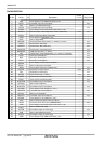
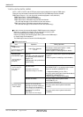
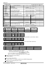
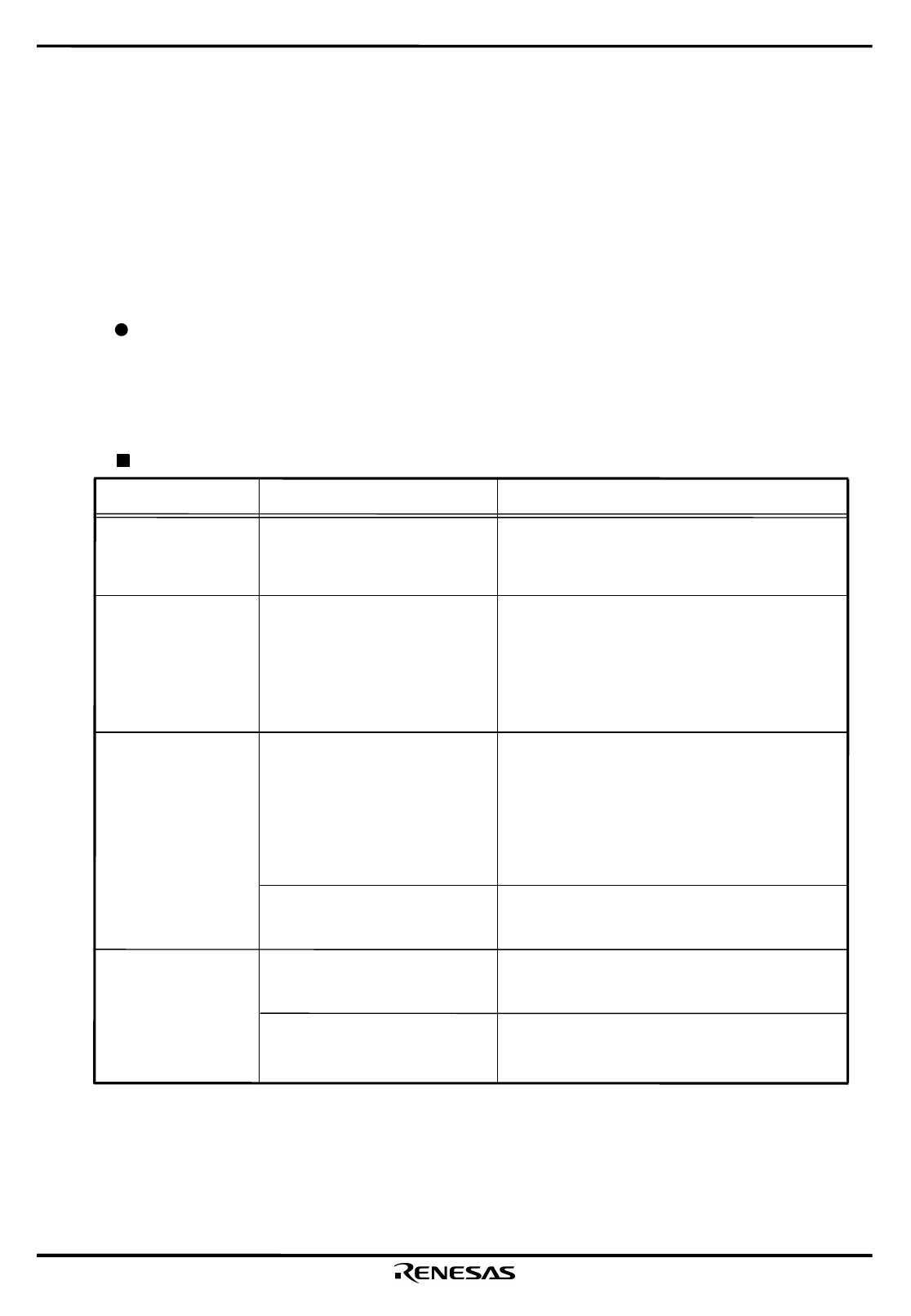
The PWM output control is shown in the following table.
PWM output control
Item
Operation
Setting Operation
Output Form
Operating Rate
and Data Bit Length
( Common setting for
Power Stage and
Headphone )
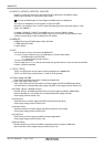
Output Muting
Reverse Output
Pins Function
Output Form Selection
1,2,3,4
Select to
16fso/6bit ,16fso/5bit ,32fso/5bit
from operating rate and data bit
length of ∆Σ.
PWM operation are synchronized
by this setting.
Duty 50% Mute
( Selectable common and
independent setting for Lch/ Rch.)
Absolute Zero Mute
Reverse on Lch and Rch of
output pins (Common setting for
Power Stage and Headphone)
Set up by the serial control system 1 mode
bit 22,23 (PWM MODE 0 and 1).
(Refer to system 1 mode(Page16) for details)
Set up by the serial control system 2 mode bit16
and bit17.
( Refer to system 2 mode(Page 18) for details.)
< Common setting for Lch / Rch >
Set NSPMUTE pin "L" or set up by serial control "
System 2 mode bit14 (NSPMUTE) "H".
< Independent Setting for Lch / Rch >
Set up by serial control Gain Control Mode bit9,10
(NSPMUTEL,NSPMUTER) "H" .
( Refer to Page 11,18 and 13 for details)
Set up by serial control system2 mode
bit15(PGMUTE) "H".
(See system2 mode(Page 18) )
Set up by serial control system2 mode bit9
(CHSEL).
Set up by serial control system2 mode bit12
(CHRSEL).
( Common setting for Power
Stage and Headphone)
Reverse for R1 and R2 of
output pins.
( Only enable for Power Stage.)
7. OUTL1, OUTL2, OUTR1, OUTR2
( Common setting for
Power Stage and
Headphone )