


6
INTRODUCTION- Technical Overview
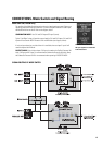
Technical Overview:
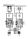
CH1 and CH2 Inputs are connected to the Top Box Processor
and to the Mode Switch. In Combination Mode, the Mode
Switch connects CH1 and CH2 Inputs to the Subwoofer
Processor as well. In Discrete Mode, CH1 and CH2 Inputs
are disconnected from the Subwoofer Processor, and Input
3 is used to feed the Subwoofer Processor.
Independent DSP is provided for each amplifier. The DSP
engines are 24-bit resolution, 48 kHz. sampling rate. They
boast less than 0.01% THD+N, 20 Hz. -20 kHz. ±0.7dB
frequency response and a dynamic range exceeding 93 dB.
All that is required is configuring the Processors with the
desired signal chain before use.
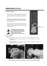
Each Processor must be configured using QSC’s Signal
Manager software, included with the 215PCM. Install the
software on a PC meeting the specified system require-
ments, then connect to the Processors (one at a time) with
an RS-232 connection and run Signal Manager. Each
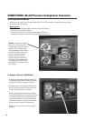
Processor has 8 Preset memories enabling the most used
configurations to be saved as convenient, easy to recall
Presets. The last applied configuration will be the power-on
default, ensuring the system powers-up in the state it was
last left. Refer to the software’s on-line Help system for
detailed information. All software related operation
information is located in Signal Manager’s Help system.
The Top Box Processor’s OUT1 and OUT2 DSP ports are
connected to the 3600 watt Top Box amplifier’s CH1 and
CH2 Inputs, respectively. The Top Box amplifier is configured
to operate in stereo mode without any filtering. All filtering
and is done in the Processor.
The Subwoofer Processor’s OUT1 DSP port is connected to
the Subwoofer amplifier’s CH1 Input. The Subwoofer
amplifier is operated in Bridge Mode. The amplifier has no
filtering. All desired processing must be done in the
Processor. The Bridge Mono outputs are wired internally to
the subwoofers.
Post Processor output connections are provided on each
Processor. These 3-pin terminal block connectors make
daisy-chaining the processed signal to other equipment a
snap.
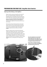
The amplifiers are modified QSC Powerlight2 models. They
feature PowerWave™ high frequency switching power
supplies for maximum performance and minimum weight.
Gain controls are preset to full, but each amplifier’s Gain
controls are accessible through small access holes in the
respective cooling air intake grill; this allows a relatively
tamper-proof maximum gain setting. The amplifiers provide
features such as soft-start inrush current limiting, tempera-
ture-tracking bias control, variable speed cooling fans, and
full output protection.
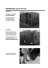
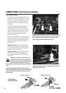
A variety of Top Box speakers are connected to the
Speakon™ connectors on the rear panel. The upper
Speakon is wired for optional biamp use (4-wire), and the
lower Speakon is wired normally (2-wire). This connection
scheme allows for biamp users to plug into one connector
for all four biamp wires, while still keeping the standard
two Speakons for two channel applications.