


26
Example 1- Discrete 2.1 (continued)
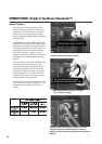
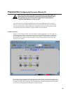
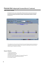
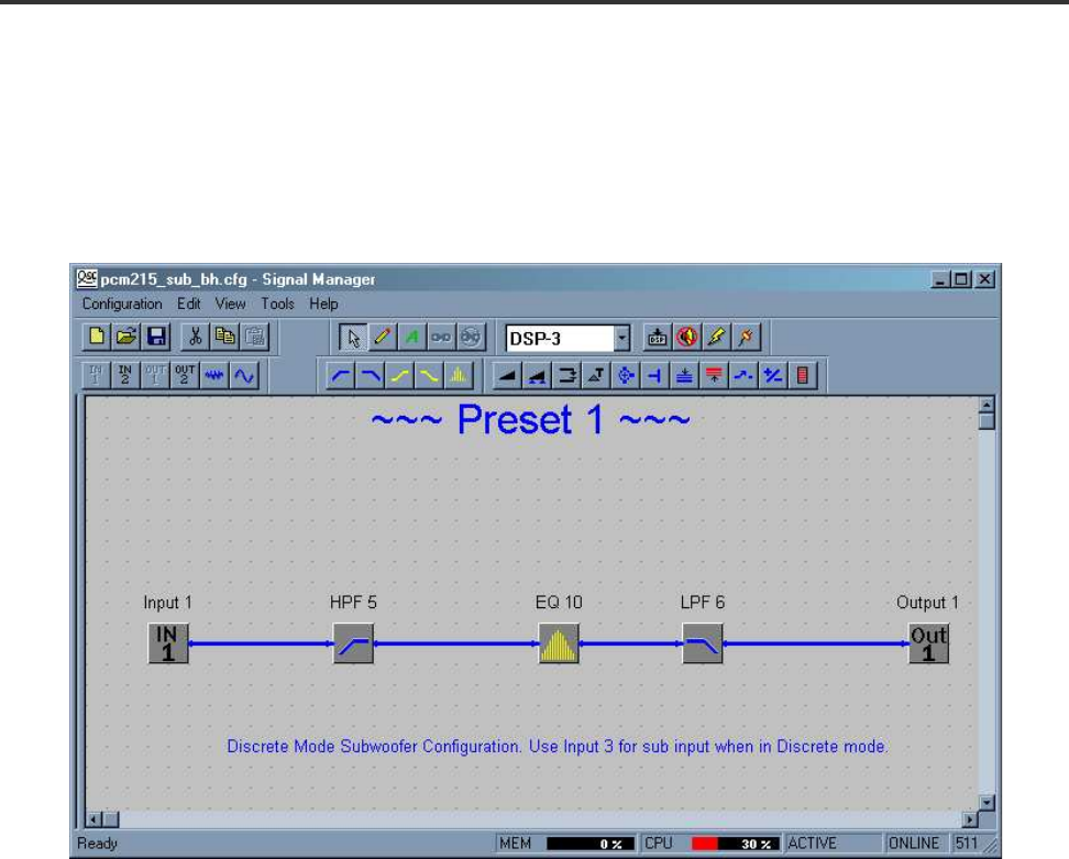
The Subwoofer Processor is next. In Discrete Mode, the Subwoofer Processor’s input signal comes from the
Input 3 XLR. Input 3 is routed to the Subwoofer Processor’s IN1 block (see example, below). The IN2 block is
not placed when operating in Discrete Mode. An example of a typical Subwoofer configuration might look
something like this:
This configuration has a high- and low-pass filter that limit the overall frequency response and equalization to
compensate for enclosure and room responses. The low-pass filter is usually tuned to remove any overlap in
frequency response of Subwoofer and Top Boxes.
Processor Use: Configuring the Processors (Discrete 2.1 continued)
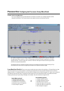
Discrete 2.1 Checklist:
1- Configure Top Box Processor.
2- Configure Subwoofer Processor.
3- Set Mode Switch to Discrete.
4- Connect the two main channel inputs to CH1 Input and CH2 Input XLRs.
5- Connect the subwoofer channel input to the Input 3 XLR.
6- Test and adjust as required.