


13
CONNECTIONS- Mode Switch and Signal Routing
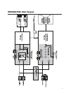
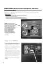
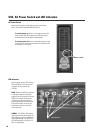
The position of the Mode Switch determines how the input signals are routed. Select your
operating mode before making connections. If you are using the DataPorts for audio input,
the Mode Switch has no effect. Refer to the diagram, below.
COMBINATION MODE– Use CH1 and CH2 Inputs OR Input 3 (mono).
Typical “Left-Right” mixes will provide a stereo feed for CH1 and CH2 Inputs. CH1 and CH2
Inputs will be routed to BOTH Processor’s IN1 and IN2 blocks (see diagram, below).
If only one input (mono) or one side of the mix is available, then use Input 3. Input 3 will
route the input to the IN1 block.
DISCRETE MODE– Use all three inputs. CH1 Input is routed to the Top Box Processor IN1
block, CH2 Input to IN2. Input 3 is connected to the Subwoofer Processor IN1 block. Note,
the Subwoofer Processor’s IN2 is not connected when operating in DISCRETE MODE.
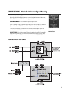
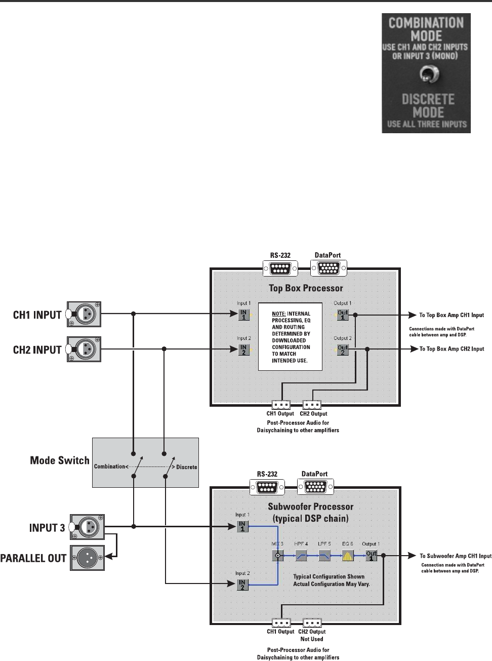
SIGNAL ROUTING BY MODE SWITCH
The mode switch effects how
the input signals are connected
to the Processors.
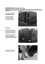
MODE SWITCH (215PCM only)