


10
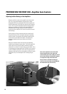
Adjusting the Gain Settings of the Amplifiers
PREPARATION FOR FIRST USE- Amplifier Gain Controls
Ordinarily, the Gain controls of the amplifiers are left set at full
gain. This is not recommended for first-time users of freely-
configurable DSP. Freely configurable DSP, while being the most
flexible and desirable, will do precisely what the user configures
it to do. This may not be the expected, desired result and could
damage your speakers or hearing. For this reason, QSC recom-
mends the initial “learning” sessions with the 215PCM be
carried out with the amplifier Gain controls set at their minimum
useful settings.
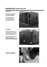
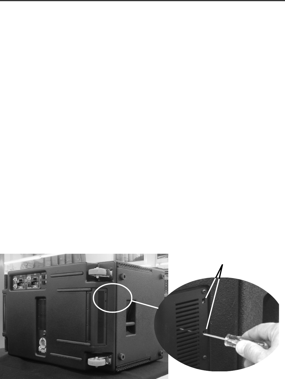
Each of the two cooling air exhaust vents (one on each end of
the cabinet) has two small, rectangular openings for adjusting
the Gain controls. The exhaust vent closest the wheels has the
access holes for the Subwoofer amplifier. The exhaust vent
closest the handles has the access holes for the Top Box
Amplifier.
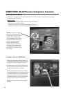
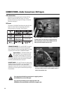
Gain control adjustment access holes (Sub-
woofer amplifier shown). The lower hole
accesses CH1’s gain control. CH2’s gain control
has no effect because the Subwoofer amplifier
is configured in bridge mono mode at the
factory. Access is available for CH2’s gain
control for users that modify the 215PCM. Note
that modifications may void warranty.
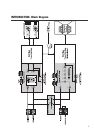
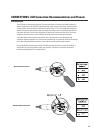
Below, the illustration shows the location of the Subwoofer
amplifier’s gain adjustment access holes. The Top Box amplifier’s
access holes are on the vent located on the other end of the
cabinet (left, as viewed). The access holes are not labeled. This is
to discourage gain tampering after the 215PCM is set up. Use a 6-
inch #1 flat blade screwdriver or similar tool. Fiberglass-shaft TV
adjustment tools work well, are nonconductive, and won’t scratch
equipment easily. Use a flashlight to aid in locating the gain
control.