


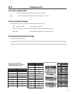

8
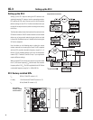
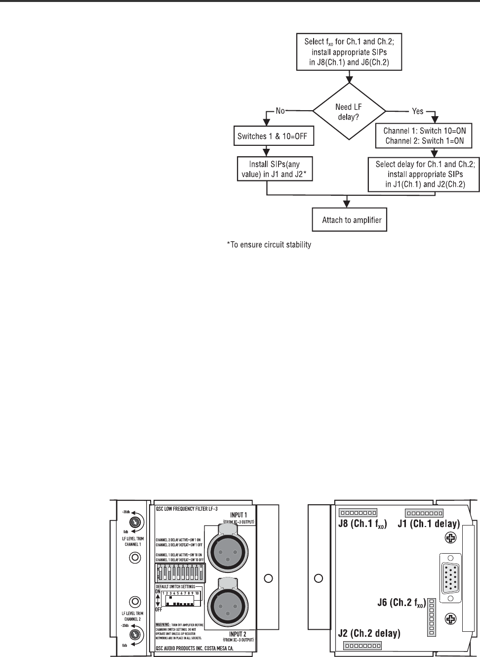
Setup flowchart for the LF-3
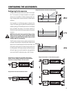
Setting up the LF-3 requires setting the DIP switches and
selecting/inserting SIP resistors into the appropriate
sockets. DIP switches #2 and #4 through #9 must be set
to OFF, and switch #3 set to ON (factory default for
proper operation). The flowchart , right, takes you through
the steps necessary before mounting the accessory to
the amp.
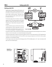
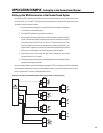
The LF-3 is typically used in a system in conjunction with
the XC-3 crossover. For example, a stereo three-way
system will require three DCA amplifiers, two XC-3’s,
and one LF-3. The typical input signal is full-range audio
taken from the XC-3’s male XLR connector labeled
“OUTPUT (TO LF-3)”.
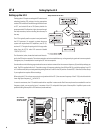
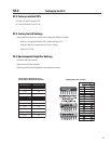
The illustration, below, shows the locations of the sock-
ets for the SIP resistor networks. The resistor networks can be inserted either way, as long as each pin goes into its own receptacle.
Straighten pins, if needed, before inserting the SIP into its receptacle.
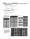
Use the tables on the following page to select the correct resistor networks for the crossover frequency (f
XO
) and delay settings you
need. The SIPs supplied with the LF-3 provide a range of frequency selections from 80 Hz to 500 Hz, and delay settings from 0.3
to 1.8 milliseconds; delay can be bypassed by putting Switches 1 and 10 in the OFF position. Contact QSC’s Technical Services Group
if your application requires different settings.
When using the LF-3 in a three-way system in conjunction with the XC-3, the crossover frequency of the LF-3 (f
XO
) should match the
lower high-pass frequency (f
HP
) of the XC-3.
In most circumstances, the LF-3 would be used with an amplifier in stereo mode. But if two amp channels are needed for one low
frequency signal, you can use the Input 1 connector of the LF-3 and parallel the inputs of the amplifier. Amplifier inputs can be
paralleled using the amplifier’s DIP switches (mode switches).
LF-3 controls,
switches, and SIP
socket locations
LF-3 Setting Up the LF-3
Setting up the LF-3