


6
XC-3 Setting up the XC-3
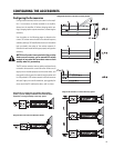
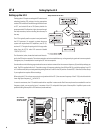
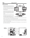
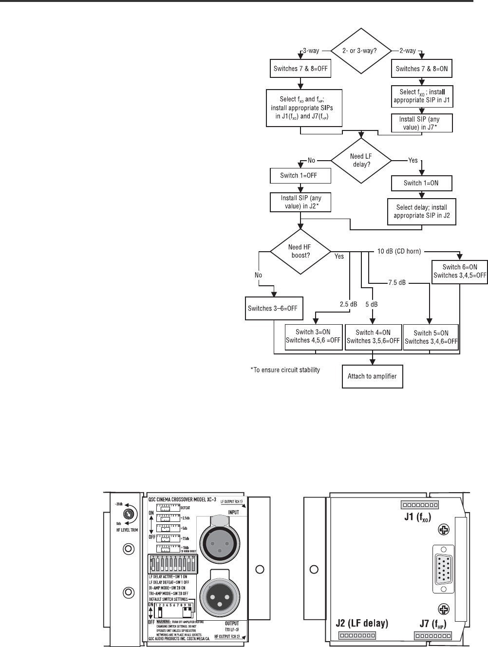
Setting up the XC-3 requires setting the DIP switches and
selecting/inserting SIP resistors into the appropriate sockets.
DIP switches #2, #9, and #10 must be set to the ON position
(default settings for the XC-3). The flowchart below takes you
through all the steps necessary before mounting the accessory
to the amp.
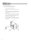
The illustration below shows the locations of the sockets for the
SIP resistor networks. The SIP resistor networks can be inserted
either way, as long as each network pin goes into its own hole
in the socket. Straighten the pins, if needed, before inserting the
SIP into its receptacle.
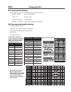
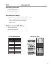
Use the tables on the following page to select the correct
resistor networks for the settings you need. The SIPs supplied
with the XC-3 provide a selectable frequency range for f
XO
of
80 Hz to 1.5 kHz, and delay settings from 0.3 to 1.8 milliseconds;
contact QSC’s Technical Services Group if your application
requires different settings.
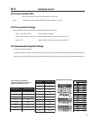
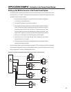
When using the XC-3 in a three-way system in conjunction with
the LF-3, the lower frequency (f
HP
) should match the crossover
frequency of the LF-3 (f
XO
). The SIPs supplied with the XC-3 allow
a selectable frequency range for f
HP
of 80 to 500 Hz.
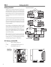
Setup flowchart for the XC-3
XC-3 controls,
switches, and SIP
socket locations
XC-3 Factory-installed SIPs
f
XO
500 Hz (12 kΩ SIP resistor in J1)
LF delay 1.8 milliseconds (27 kΩ SIP resistor in J2)
f
HP
80 Hz (68 kΩ SIP resistor in J7)
Setting up the XC-3