


10
Setting up the SF-3
SF-3 Setting up the SF-3
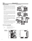
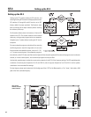
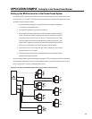
Setting up the SF-3 requires setting the DIP switches, and
selecting/inserting SIP resistors into the appropriate sockets.
DIP switches #1 through #6 and #10 must be set to OFF
(factory default for proper operation). The flowchart, right,
takes you through all the steps necessary before mounting
the accessory to the amp.
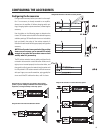
The illustration below shows the locations of the two SIP
sockets on the SF-3. The resistor networks can be inserted
either way, as long as each pin goes into its own receptacle.
Straighten pins, if needed, before inserting the SIP into its
receptacle.
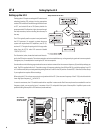
The mono subwoofer program can be derived from summing
and filtering stereo or mono full-range audio or it can come
from a discrete mono subwoofer channel, such as in a 5.1, 6.1,
or 7.1 cinema surround system. If the subwoofer program is
to be derived, use the SF-3’s low-pass filter to set the high end of the subwoofer passband. If the subwoofer program source is a discrete
channel, as in most cinema systems, we recommend you bypass the low-pass filter.
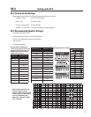
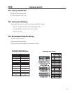
Use the table, opposite page, to select the correct resistor networks for the SF-3’s filter frequency settings. The SIPs supplied provide
a selection of three low-pass frequencies: 80, 150, and 250 Hz; and six high-pass frequencies from 20 to 50 Hz. Use the speaker
manufacturer’s recommended filter settings.
The low-frequency boost switch selects the Q of the high-pass filter: 0.707 for flat (Butterworth), or 2 for “boost,” which adds a 6 dB
peak at the filter’s selected frequency.
SF-3 controls,
switches, and SIP
socket locations