


Tsunami MP.11a Antenna Installation Guide
General Description......................................................................................................................................44
Mounting Instructions....................................................................................................................................44
Specifications ...............................................................................................................................................45
Pattern ..........................................................................................................................................................45
23 dBi HIGH GAIN DIRECTIONAL PANEL ANTENNA for 5.8 GHz....................................................................46
Package Contents ........................................................................................................................................46
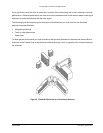
Mounting.......................................................................................................................................................46
Specifications ...............................................................................................................................................47
Pattern ..........................................................................................................................................................48
APPENDIX D. CERTIFIED OUTDOOR SOLUTIONS ...............................................................................................50
Introduction ..........................................................................................................................................................50
Selecting the Correct Cables ...............................................................................................................................50
APPENDIX E. CHANNEL FREQUENCIES...............................................................................................................51
SUPPORT AND WARRANTY ....................................................................................................................................52
Technical Support................................................................................................................................................52
Warranty and Repair............................................................................................................................................53
Figure 1. Point-to-Point Link ....................................................................................................................... 6
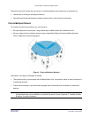
Figure 2. Point-to-Multipoint Network ......................................................................................................... 7
Figure 3. Cable Setup for Indoor Installation.............................................................................................. 9
Figure 4. Potential Obstacles for a Directional Antenna .......................................................................... 13
Figure 5. Fresnel Zone ............................................................................................................................. 18
Figure 6. Clearance Factor Diagram ........................................................................................................ 20
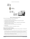
Figure 7. Surge Arrestor ........................................................................................................................... 36
Table 1. Cable Factor ............................................................................................................................... 17
Table 2. Receiver Sensitivity and Minimum SNR for a Good Link ........................................................... 23
Table 3. Output Power Table for FCC...................................................................................................... 23
Table 4. Output Power Table for ETSI ..................................................................................................... 24
Table 5. Examples of Antenna Cable Loss Required per Regulatory Domain and Antenna Type........... 24
Table 6. Distance and Link Budget........................................................................................................... 25
Table 7. Antenna List................................................................................................................................ 33
Table 8. Standard N-Type Connector Diagram........................................................................................ 34
Table 9. Reverse Polarity-N Cabling Diagram ......................................................................................... 35
Table 10. Specifications: Surge Arrestor................................................................................................. 37
Table 11. Specifications 6 m (20 ft) Antenna Cable ................................................................................. 38
Table 12. Specifications 15 m (50 ft) Antenna Cable ............................................................................... 38
Table 13. Specifications 22 m (75 ft) Antenna Cable ............................................................................... 39
Table 14. Specifications 15 m (50 ft) Extra Low Loss Antenna Cable ..................................................... 39
Contents 4
CPN 65756B Issue Date: August 2003