


Tsunami MP.11a Antenna Installation Guide
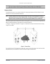
In Figure 5, you see two variables that determine the shape of the antenna beam, also referred to as Fresnel
Zone:
▪ The distance between the antennas (a)
▪ The clearance required for optimal performance (b), where clearance should be interpreted as:
º Vertical clearance above the ground and the highest buildings or objects in the signal path
º Horizontal clearance from neighboring buildings and objects in the signal path.
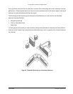
For optimal range and throughput performance, you must ensure that your antenna installation provides
maximum clearance in both horizontal and vertical direction.
Clearance should be interpreted as follows:
▪ In open areas without obstacles in the signal path, clearance is measured as height above the surface of
the earth. For example, if the antenna is mounted on the roof, this height includes the height of the
building plus the height of the mast above the rooftop.
▪ In areas with obstacles in the signal path between the two antennas, clearance should be measured as
height above the highest obstacle in the signal path.
▪ In dense urban areas, the clearance should be measured as height above the highest rooftop or any
other obstacles in the signal path between the two antennas.
For situations in which local authorities, the proprietor of the premises, or other factors do not let you set up
an antenna mast that lets you meet the listed clearance requirements, you may be unable to achieve a full
line-of-sight clearance. At the same time, however, when the distance that your wireless outdoor installation
must cover is less than the listed maximum range, you may not even need full clearance,.
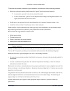
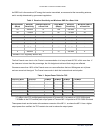
To determine the effect of insufficient signal path clearance, you must determine the Clearance Factor as
described below, and calculate its effect on the range for your antenna installation using the formula
described in “Determining the Outdoor Range” on page 16.
▪ If the clearance for your antenna installation is equal to or better than the minimum clearance
requirement, the Clearance Factor for your installation is 100%.
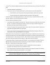
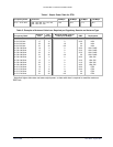
▪ If your actual clearance is less than the minimum clearance, use the diagram depicted in the following
figure to determine the actual range that applies in your situation.
Note: The Clearance Factor Diagram should be used as a rule-of-thumb for estimating the probable range
in case the clearance requirements are not fully met. In real life, using FCC approved products, you
will also find it almost impossible to achieve the level of clearance for maximum range.
Chapter 2. Determining Range and Clearance 19
CPN 65756B Issue Date: August 2003