


Tsunami MP.11a Antenna Installation Guide
Note: Previously marketed Tsunami outdoor antenna systems in FCC regulated countries (such as the
USA and Canada) were shipped with a different cabling system, identified by reverse polarity-N
connectors (depicted in the following table).
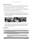
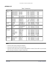
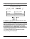
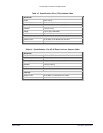
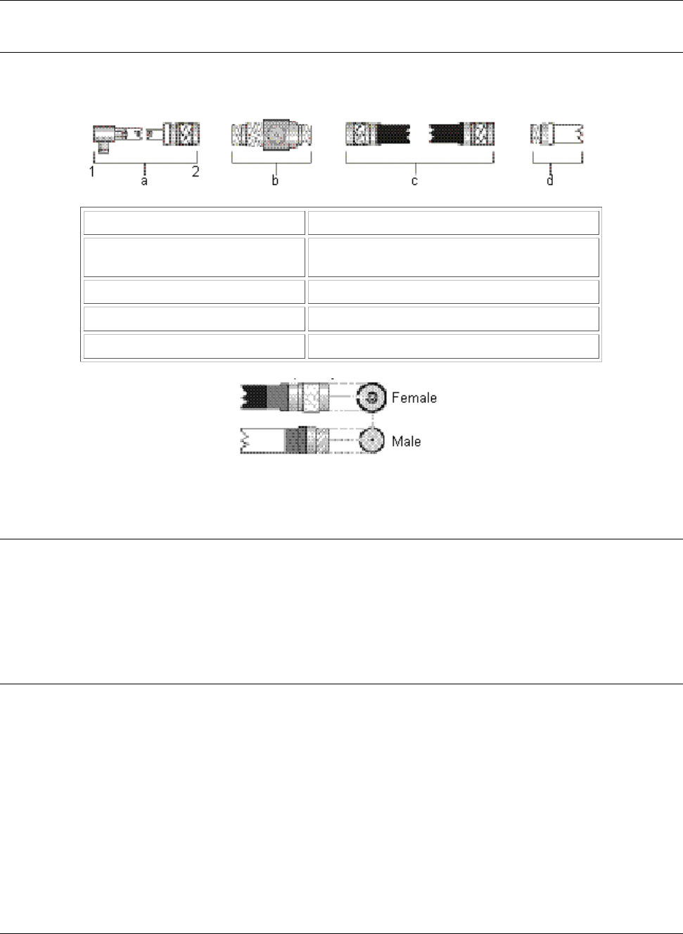
Table 9. Reverse Polarity-N Cabling Diagram
Cabling Component Reverse Polarity-N Cabling Systems
a Pigtail attached to MP.11 1 Proprietary connector
2 Reverse polarity-N male
b Surge arrestor Reverse polarity-N female on both ends
c Low-loss cable Reverse Polarity-N male on both ends
d Outdoor antenna Reverse polarity-N female
Note that the gender of the connector is not determined by the connector’s thread, but by its center pin; a
solid center pin = male, a hollow pin = female.
DANGER!
Outdoor antennas and antenna cables are electrical conductors. Transients or electrostatic discharges that may
occur at the antenna (for example a lightning strike during thunderstorms) may damage your electronic
equipment and cause personal injury or death to persons touching the exposed metal connectors of the antenna
cable.
To avoid damage and personal injury, the entire antenna cabling system must be grounded at all times.
When installing, disconnecting or replacing one of the cabling components, you must ensure at all times that
each exposed metal connectors of the antenna cabling system will be grounded locally during the work.
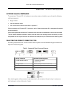
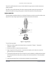
For example when mounting or replacing the surge arrestor:
1. First connect each of the connectors of the low-loss antenna cables to the grounding system.
2. Next connect the cable connector to the grounding system.
3. Finally connect the surge arrestor to the grounding system.
Before you proceed, verify that each of the items is properly grounded and that the ground will not
interrupted when disconnecting one of the antenna system components.
Appendix B. Antenna Cabling System 35
CPN 65756B Issue Date: August 2003