


For Customer Service, call 800-377-7655.
7
6
Get more information and exclusive accessories, visit www.polkaudio.com
• Your Atrium Powered Speaker can be either
the left or right speaker of a stereo pair,
depending on convenient placement near a
standard household AC power source. Use
the “balance” control of your electronics to
send the signal alternately to the left and
then to the right. If you find stereo imaging
is “backwards” after you’ve hooked up the
Speaker Wire inputs, simply switch the Left
& Right inputs to flip-flop the Left & Right
images. Be sure to maintain terminal color
consistency (polarity).
• Use speaker wire of the correct length to
attach the Powered Speaker to its Passive
partner via Binding Post connections
[figures 9 & 10].
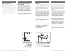
• Only after you have made your speaker
connections, attach the External AC Power
Pack to the Powered Speaker [figure 11].
Plug the Power Pack into a standard house-
hold AC power source, and then turn on
your electronics.
SELECTING AN ELECTRONIC SOURCE
If you turn on your system and do not
hear any sound, check the settings on
your electronics.
• Make sure the “Mute” option is
not selected.
• If your receiver has “Multi-Zone” controls,
make sure the correct options have
been selected.
• If your receiver has an “A” & “B” speaker
selector for “Multi-Room” use, make sure
the correct option is selected.
• If only one speaker is working, check the
balance control setting on your receiver
or amplifier.
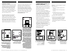
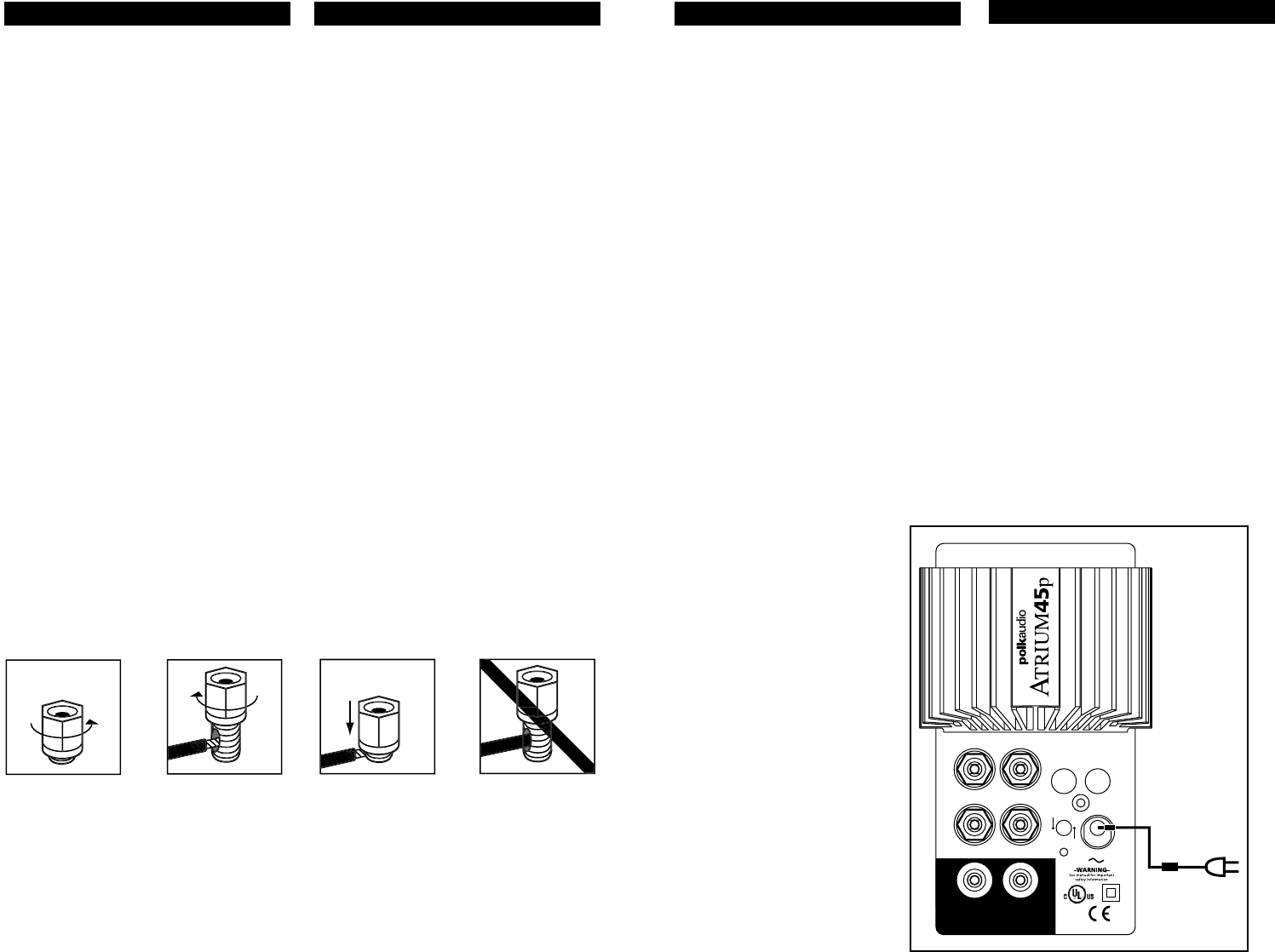
FIGURE 11
Back panel of Powered Atrium speaker.
Panel posterior del altavoz alimentado Atrium.
Panneau arrière de l'enceinte Atrium amplifiée.
Rückseite des Atrium-Powered-Lautsprechers.
INPUT 1
INPUT 2
OUTPUT TO PASSIVE SPEAKER
LINE LEVEL IN
—
+
—
+
12
MONO
STEREO
18VAC
AC
• Your Atrium Powered Speaker can be either
the left or right speaker of a stereo pair,
depending on convenient placement near
a standard household AC power source.
Use the “balance” control of your electron-
ics to send the signal alternately to the left
and then to the right. If you find stereo
imaging is “backwards” after you’ve hooked
up the Line Level inputs, simply switch the
1 & 2 inputs to flip-flop the Left & Right
stereo images.
• Use speaker wire of the correct length to
attach the Powered Speaker to its Passive
partner via Binding Post connections [fig-
ures 9 & 10].
• Only after you have made your speaker
connections, attach the External AC Power
Pack to the Powered Speaker [figure 16].
Plug the Power Pack into a standard
household AC power source, and then
turn on your electronics.
Hookup Hookup #2—Speaker Wire [figure
8]. Use this hookup method with speaker
wire to remote locations, for “Multi-Room”
(selectable “A” or “B” speaker-set on your
electronics) applications.
• Turn your source electronics off.
• Attach Speaker Wire from your receiver
or amplifier to the Left and Right Speaker
Wire Input Posts on the back panel of the
Self-Powered Atrium Powered Speaker.
• Strip 2 inch (12.7mm) of insulation from
each of the two conductors of the wire to
expose the bare metal and twist each of the
conductors into a single unfrayed strand
(so you have two unfrayed strands). Note
that one of the terminals on the rear of the
speaker is red (+) and the other is black
(-). Make certain that you connect the wire
from the red terminal of your amplifier or
receiver to the red terminal on your
speaker and the wire from the black
terminal of your amplifier or receiver to
the black terminal on your speaker [figure
11]. Most wire has some indicator (such
as color-coding, ribbing or writing) on
one of the two conductors to help you
maintain consistency.
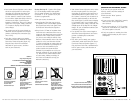
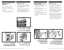
Insert speaker wire
through hole
Inserte el alambre para la
bocina en el orificio
Insérer le fil du haut-parleur
dans le trou
Lautsprecher-Draht durch
das Loch schieben
Loosen hex nut
Desenrosque parcialmente
la tuerca hexagonal
Desserrer l’écrou
Sechskantmutter lösen
Tighten hex nut
Enrosque la tuerca de nuevo
Serrer l’écrou
Sechskantmutter festschrauben
Do not insert insulated
section of speaker wire
No inserte alambre con
material aislante
Ne pas insérer la partie
isolée du fil du haut-parleur
Isolation des Lautsprecher-
Drahtes nicht in das Loch
schieben
FIGURE 10
Using 5-Way Binding Posts
EL USO DE POSTES DE CONEXIÓN DE CINCO
POSICIONES
UTILISATION DES BORNIERS
“CINQ FAÇONS”
GEBRAUCH VON FÜNFER-VERBINDUNGSBOLZEN