


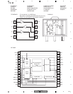
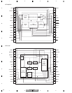
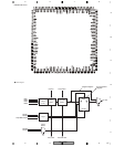
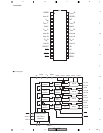
RS-A9/EW
126
1234
1234
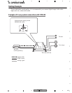
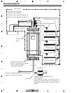
C
D
F
A
B
E
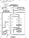
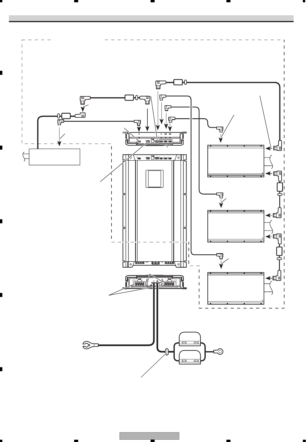
Connection Diagram
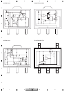
*1 IP-BUS cable (supplied)
*2 Optical cable (supplied)
*3 IP-BUS cable (supplied with RS-A7)
*4 Optical cable (supplied with RS-A7)
*1
*3
*3
*3
*2
*4
*4
*4
Optical input
Optical out
Speaker output terminal
See the “Connecting the Speaker
wires” section for speaker
connection instructions.
RS-A7
(sold separately)
IP-BUS input
(blue)
Black
To optical input
To optical input (blue)
To IP-BUS input (blue)
(blue)
(black)
Fuse (25 A)
Optical out (Black)
IP-BUS out (black)
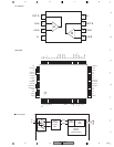
Ground wire (Black) [RD-223] (sold separately)
Connect to metal body or chassis.
fuse (30 A) 2
6 m1 m
RS-A7
(sold separately)
RS-A7
(sold separately)
Special red battery wire [RD-223]
(sold separately)
After making all other connections at the
amplifier, connect the battery wire terminal of
the amplifier to the positive (+) terminal of the
battery.
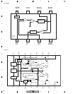
(blue)
(black)
To optical input
Red
Audio system
Grommet