


RS-A9/EW
102
1234
1234
C
D
F
A
B
E
6. ADJUSTMENT
6.1 AMP UNIT ADJUSTMENT
Remarks
Both items are adjustable if the bottom plate of the product is removed to expose the unit.
Adjustment is capable using half-fixed resistance, by inserting the precise driver
into a hole on the base plate from its surface B.
When adjusting offset voltage--- VR1101, VR1201, VR1301, VR1401
When adjusting idling current--- VR1102, VR1202, VR1302, VR1402
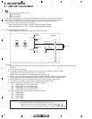
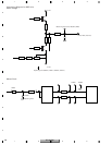
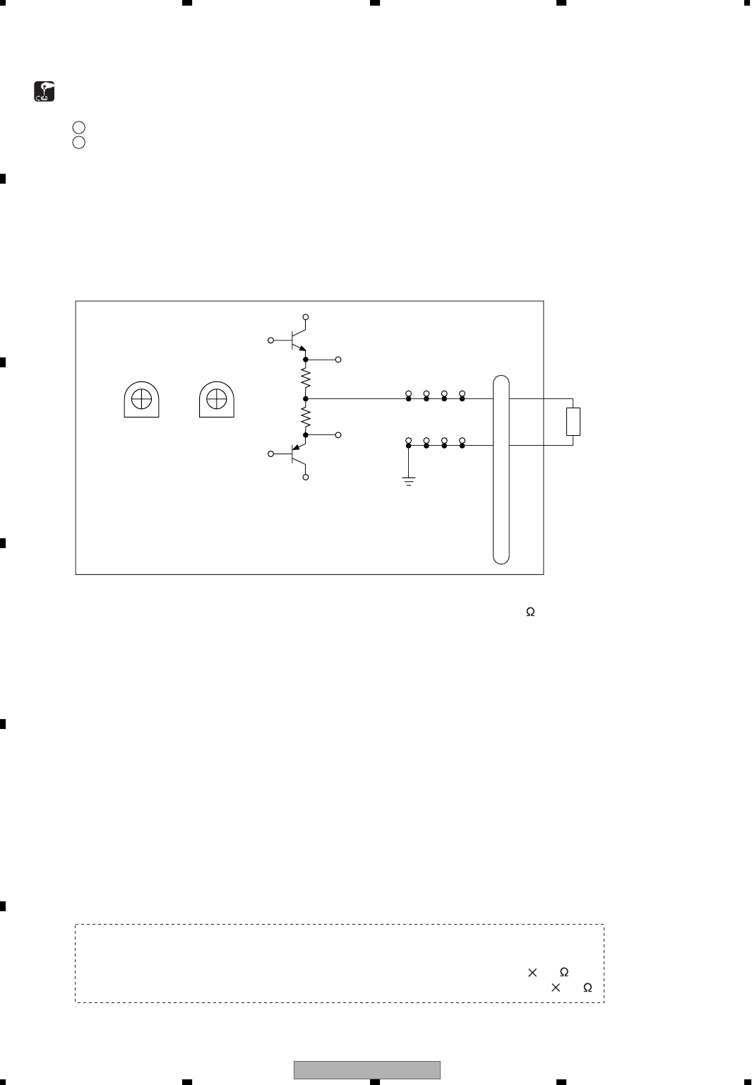
Connecting Diagram for AMP Unit
[Offset Voltage/Idling Current Adjustment and Confirmation]
AMP Unit
0
3
4
2
1
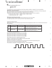
When adjusting and confirming the offset voltage/idling current, connect 4 load to the speaker output
terminal.
Input must be non-signal.
For adjusting offset voltage, coarsely control with VR1101, VR1201, VR1301, VR1401
immediately after powering ON, within 3 or 4 minutes.
Idling current must also be coarsely adjusted at the same time.
Idling current must be adjusted with VR1102, VR1202, VR1302, VR1402 immediately after
the completion of offset voltage adjustment (within 4 or 5 minutes after powering ON).
Both adjustments must be completed within 3 to 5 minutes after powering ON.
For confirming, measure "within 3 to 5 minutes" after powering ON.
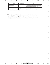
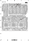
Measuring points for Rated Value No.13 (offset voltage)
AL (CN66-CN95) or its equivalent land
AR (CN48-CN83) or its equivalent land
BL (CN60-CN91) or its equivalent land
BR (CN54-CN87) or its equivalent land
Measuring points for Rated Value No.14 (idling current)
AL (CN63-CN64)
AR (CN45-CN46)
BL (CN57-CN58)
BR (CN51-CN52)
1
2
3
4
5
6
7
8
The voltage between R1129 and R1130 as shown in the above diagram
is to be measured so as to adjust the idling current in:
*When mounted on main Main Heat Sink --- 30mV (150mA 0.2 )
*When not mounted on main Main Heat Sink --- 20mV (100mA 0.2 )
Postscript)
The items for adjusting AMP unit are:
1
Offset Voltage
2
Idling Voltage
CN1101
Q1119
2SC4886
Q1120
2SA1860
R1129
0.1
Iidle
VR1102
2.2k
VR1101
1k
Voffset
R1130
0.1
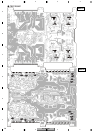
CN45
CN46
CN83 CN85
CN84 CN86
CN48 CN50
CN49 CN69
4ohm load
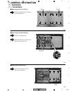
Refer to the 126 pages for connection of the system at the time of adjustment and repair.