


PARTS AND THEIR FUNCTIONS
22
En
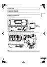
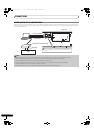
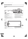
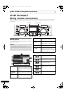
REAR PANEL
Drive Unit
1 AC inlet (AC IN)
Use the supplied power cord to connect this inlet to a
household AC outlet.
2 PC connector: USB port (type B)
Use the supplied USB cable to connect this port to a
computer.
3 USB1 port (type A)
Use to connect a USB storage device or USB keyboard.
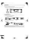
4 Digital output connectors (DIGITAL OUT A/B)
RCA-type coaxial digital output connector for connecting a DJ
mixer, AV amplifier, CD recorder or other component
supporting digital input.
The output supports all functions including DJ function, but
only audio data not including subcodes is output.
5 Control jacks (CONTROL A/B)
When the supplied control cord is used to connect this unit to
a Pioneer DJ mixer, the DJ mixer can be used to control this
unit so as to perform fader start play and back cue operations.
Also, by connecting this jack to another DJ player’s control
jack, automated relay play can be performed.*
* Relay play is disabled during DJ software track selection.
6 Audio output connectors (AUDIO OUT A/B)
RCA-type analog audio output connectors.
7 Remote control connector (REMOTE CONTROL)
Use the supplied dedicated remote control cable to connect to
the control unit.
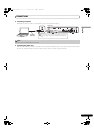
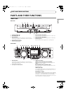
Control Unit
1 PC connector: USB port (type B)
Use the accessory USB cable to connect this port to a
computer.
2 5 V connector
Use the accessory USB auxiliary power cable to connect to a
computer.
3 Video output connector (MONITOR OUT)
Use a video cable to connect to an external display.
4 Remote control connector (REMOTE CONTROL)
Use the supplied dedicated remote control cable to connect to
the drive unit.
AC IN
AB
DIGITAL OUT
REMOTE
CONTROL
AB
AUDIO OUTAUDIO OUT
L
R
CONTROL CONTROL
L
R
USB1PC
1 23 4 76
5
PC
MONITOR OUT
5V
REMOTE
CONTROL
1
2
3
4
MEP-7000_7L_EN.book 22 ページ 2008年3月5日 水曜日 午後6時4分