


Black plate (12,1)
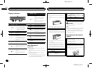
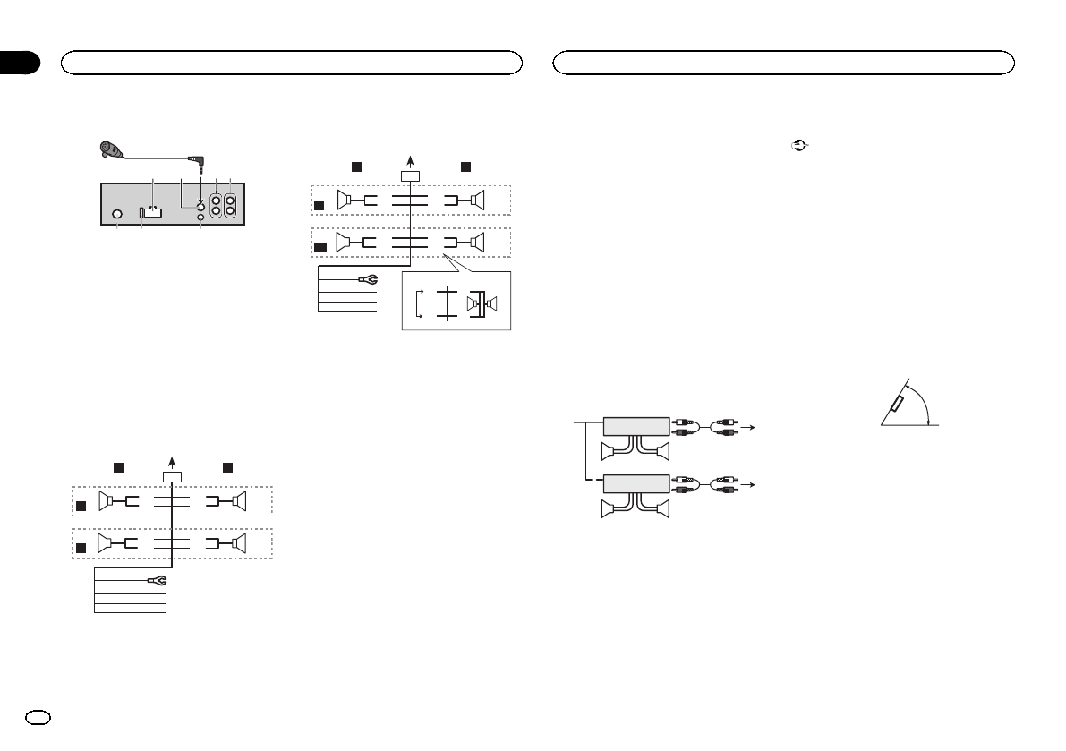
This unit
1
3
2
6
7 8
4 5
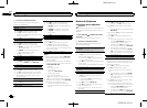
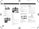
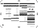
1 Power cord input
2 Microphoneinput
3 Microphone
4 Rearoutput or subwoofer output
5 Front output
6 Antenna input
7 Fuse (10 A)
8 Wiredremote input
Hard-wired remote control adaptor can be
connected (sold separately).
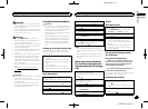
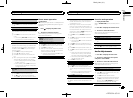
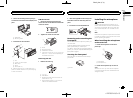
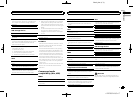
Power cord
Perform these connections when not connect-
ing a rear speaker lead to a subwoofer.
1
8
9
c
d
6
32
4
5
7
a
b
e
f
h
g
LR
F
R
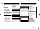
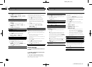
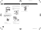
Perform these connections when using asub-
woofer without the optional amplifier.
1
8
9
c
d
6
32
4
7
a
b
a
b
e
f
h
g
LR
F
SW
i
j
d
c
k l
1 Topower cord input
2 Left
3 Right
4 Front speaker
5 Rearspeaker
6 White
7 White/black
8 Gray
9 Gray/black
a Green
b Green/black
c Violet
d Violet/black
e Black(chassis ground)
Connect to a clean, paint-free metallocation.
f Yellow
Connect to the constant 12 V supplytermi-
nal.
g Red
Connect to terminal controlled by ignition
switch (12 V DC).
h Blue/white
Connect to system control terminal of the
power amp or auto-antenna relay control ter-
minal (max. 300 mA 12 V DC).
i Subwoofer(4 Ω)
j Whenusing a subwoofer of 70 W (2 Ω), be
sure to connect the subwoofer to the violet
and violet/black leads of this unit. Do not
connect anything to the green and green/
black leads.
k Not used.
l Subwoofer(4 Ω)× 2
Notes
! With a 2 speaker system, donot connect any-
thing to the speaker leads that arenot con-
nected to speakers.
! Change the initial setting of this unit. Refer
to SW CONTROL (rear output and subwoofer
setting) on page 10.
The subwoofer output of this unit is monau-
ral.
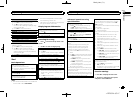
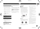
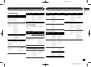
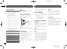
Power amp (sold separately)
Perform these connections when using theop-
tional amplifier.
1
1
3
2
4
55
3
2
6
77
1 System remotecontrol
Connect to Blue/white cable.
2 Power amp (sold separately)
3 Connectwith RCA cables (sold separately)
4 ToRear output or subwoofer output
5 Rearspeaker or subwoofer
6 ToFront output
7 Front speaker
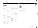
Installation
Important
! Check all connections and systems before
final installation.
! Do not use unauthorized parts as this may
cause malfunctions.
! Consult your dealer if installation requires
drilling of holes or other modifications to the
vehicle.
! Do not install this unit where:
— itmay interfere withoperation of the vehicle.
— itmay cause injury to apassenger as aresult
of asudden stop.
! The semiconductor laser will be damaged if
it overheats. Install this unit away fromhot
places such as near the heater outlet.
! Optimum performance is obtained when the
unit is installed at an angle of lessthan 60°.
60°
DIN front/rear mount
This unit can be properly installed using either
front-mount or rear-mount installation.
Use commercially available parts when instal-
ling.
DIN Front-mount
1 Insert the mounting sleeve into the dash-
board.
For installation inshallow spaces, use the sup-
plied mounting sleeve. If there is enough space,
use the mounting sleeve that came withthe ve-
hicle.
Installation
03
12
Section
Installation
En
<YRD5324-A/S>12