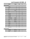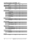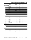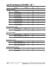
CLD-V2800 Control Blocks
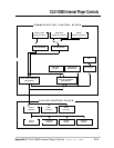
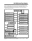
The following control blocks are used within the CLD-V2800.
1.) Communication control block
2.) Player control block
1) Communication control block
The communication control block is divided into eleven units. It analyzes
commands sent via various input methods, and executes the commands.
Front Panel Buttons
The CLD-V2800 has these buttons on the front panel: POWER ON, CD-
OPEN/CLOSE, LD-OPEN/CLOSE, PLAY/PAUSE, STILL/STEP FORWARD &
REVERSE, SKIP/SCAN FORWARD& REVERSE, and STOP .
Wireless Remote Control Unit
This is the remote sensor on the front panel. It converts the infrared Barcode
or RCU code to an electric signal.
Wired Remote Control Unit
This is the Barcode terminal on the front panel. It receives the Barcode or
RCU code via the stereo pin jack.
Head Phone Jack (CLD-V2600 only)
This is the jack for a headphone on the front panel. There is also a volume
control.
Key Decoder
When a front panel button (key) is pressed, the key decoder generates data
corresponding to the pressed button and sends it to the Key/RCU Command
Processor.
RCU Decoder
When an RCU button (key) is pressed, the RCU decoder generates data
corresponding to the pressed button and sends it to the Key/RCU Command
Processor.
Key/RCU Command Processor
This command processor analyzes the front panel button /RCU command
data received from the Key Decoder or the RCU Decoder, for execution.
RS-232C Command Processor
The RS-232C command processor analyzes RS-232C command data received
from the RS-232C buffer for execution.
RS-232C Buffer Unit
The RS-232C buffer unit receives input from the 15-pin D-SUB connector on
the rear panel. The unit consists of an input command data buffer and an
output status data buffer.
CLD-V2800 Internal Player Controls
Appendix C
CLD-V2800 Internal Player Controls
TP 120 v. 1.0 • 10/95
C-1


