


5
<ARE7263>
En
English
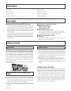
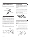
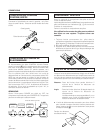
1. Strip off the vinyl covering and twist the tip of the
wire core.
2. Loosen the knob and insert the wire core into the
terminal hole.
3. Tighten the knob to fix the wire core in place.
CONNECTING THE SPEAKER CORDS
10mm
Twist the wire core.
NOTE:
Do not allow any of the cord conductors to protrude from the
terminals or touch any other conductors. Malfunctioning or
breakdowns may occur when conductors come into contact
with each other.
Speaker Impedance
When speaker systems are connected to only SPEAKERS A
or SPEAKERS B terminals, such speakers should have rated
impedance in the range of 4–16 Ω.
When speaker are connected to both A and B terminals, they
should have a rated impedance in the range of 8 –32 Ω.
\
3
2
1
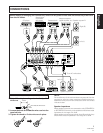
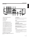
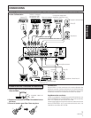
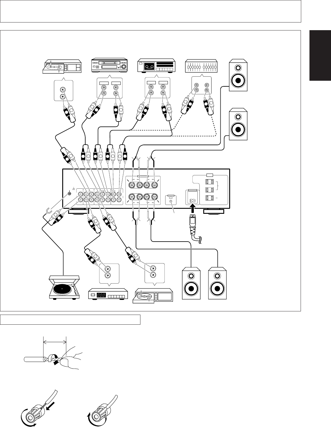
CONNECTIONS
Before making or changing the connections, switch off the power switch and disconnect the power cord
from the AC outlet.
To an AC wall socket.
See page 6.
Left (L)
Speaker system A
Right (R)
Turntable
SPEAKERS
RL
R
A
B
L
ª · · ª
SIGNAL
GND
L
R
PHONO
IN
TUNER
IN
CD
IN
LINE/
SURROUND
BACK
IN
TAPE 1/CD-R/MD
REC PLAY REC PLAY
TAPE 2 MONITOR
OUT INOUT IN
L
R
AC INLET
REC
PLAY
L
R
REC
PLAY
L
R
CD
OUT
L
R
IN
OUT
L
R
FM-AM
OUT
L
R
L
R
L
R
ª
·
ª·
L
L
R
R
L
R
L
R
L
R
L
R
ª
·
ª
AUDIO OUT
L
R
L
R
L
R
L
R
MINIDISC
CONTROL
OUT
R
L
R
L
R
L
·
L
R
L
L
R
R
AC 120 V 60 Hz
SWITCHED
TOTAL
100W MAX
UNSWITCHED
100W MAX
AC
OUTLETS
CAUTION:
DO NOT CONNECT
TV SET OR MONITOR.
ATTENTION:
NE RELIEZ PAS
AL'APPAREIL
DE TELEVISION
OU AU MONITEUR.
DVD
Cassette deck/
CD recorder/
MD recorder
Tuner DVD player, VCR, etc.
Speaker system B
Adaptor component
(graphic equalizer, etc.)
Cassette deckCD player
Right (R)
Left (L)