


TZA3046_1 © Koninklijke Philips Electronics N.V. 2006. All rights reserved.
Product data sheet Rev. 01 — 19 May 2006 9 of 15
Philips Semiconductors
TZA3046
Fiber Channel/Gigabit Ethernet transimpedance amplifier
[1] Guaranteed by design.
[2] Max input current is guaranteed for BER < 10
−10
[3] Max input current is guaranteed for T
amb
= 25°
[4] Max value of 500 mV belongs to I
PIN
= 1250 µA (p-p)
Bias voltage: pad DREF
R
(DREF-VCC)
resistance between pin
DREF and pin V
CC
tested at DC level;
T
amb
=25°C
260 290 320 Ω
TC
RDREF
temperature coefficient of
R
DREF
- 0.33 - Ω/°C
Input: pad IPHOTO
I
IPHOTO(p-p)
peak-to-peak current on
pad IPHOTO
[2][3]
−1000 +1700 - µA
V
bias(i)
input bias voltage 700 850 1000 mV
Monitor: pad IDREF_MON
V
mon
monitor voltage 0 - V
CC
− 0.4 V
I
IDREF_MON
/I
DREF
monitor current ratio ratio I
IDREF_MON
/ I
DREF
19.5 20 20.5 %
I
offset(mon)
monitor offset current T
amb
=25°C 0 10 20 µA
TC
I(offset)mon
temperature coefficient of
monitor offset current
- 30 - nA/°C
Data outputs: pads OUT and OUTQ
V
O(cm)
common mode output
voltage
AC-coupled; R
L(dif)
= 100 Ω -V
CC
− 1.2 - V
V
o(dif)(p-p)
peak-to-peak differential
output voltage
AC-coupled; R
L(dif)
= 100 Ω
I
PIN
= 2.5 µA (p-p) × R
tr
14 19 - mV
I
PIN
= 100 µA (p-p) - 120 - mV
I
PIN
= 1500 µA (p-p)
[4]
- 325 600 mV
R
O(dif)
differential output
resistance
tested at DC level - 100 - Ω
t
r
rise time 20 % to 80 %;
I
PIN
= 100 µA (p-p)
- 150 - ps
t
f
fall time 80 % to 20 %;
I
PIN
= 100 µA (p-p)
- 150 - ps
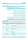
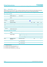
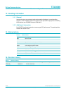
Table 4: Characteristics
…continued
Typical values at T
j
=25
°
C and V
CC
= 3.3 V; minimum and maximum values are valid over the entire ambient temperature
range and supply voltage range; all voltages are measured with respect to ground; unless otherwise specified.
Symbol Parameter Conditions Min Typ Max Unit