


Philips Semiconductors
TDA8943SF
6 W mono Bridge Tied Load (BTL) audio amplifier
Product specification Rev. 02 — 7 April 2000 7 of 20
9397 750 06865
© Philips Electronics N.V. 2000. All rights reserved.
10. Thermal characteristics
11. Static characteristics
[1] With a load connected at the outputs the quiescent current will increase, the maximum of this increase being equal to the differential
output voltage offset (∆V
OUT
) divided by the load resistance (R
L
).
[2] The DC output voltage with respect to ground is approximately 0.5V
CC
.
[3] ∆V
OUT
= | V
OUT+
− V
OUT−
|.
Table 6: Thermal characteristics
Symbol Parameter Conditions Value Unit
R
th(j-a)
thermal resistance from junction to ambient in free air 68 K/W
R
th(j-mb)
thermal resistance from junction to mounting base in free air 18 K/W
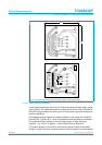
Table 7: Static characteristics
V
CC
=12V; T
amb
=25
°
C; R
L
=8
Ω
; V
MODE
=0V; V
i
= 0 V; measured in test circuit Figure 13; unless otherwise specified.
Symbol Parameter Conditions Min Typ Max Unit
V
CC
supply voltage operating 6 12 18 V
I
q
quiescent supply current R
L
= ∞
[1]
- 1522mA
I
stb
standby supply current V
MODE
=V
CC
--10µA
V
O
DC output voltage
[2]
-6-V
∆V
OUT
[3]
differential output voltage offset - - 200 mV
V
MODE
mode selection input voltage operating mode 0 - 0.5 V
mute mode 3 - V
CC
− 1.5 V
standby mode V
CC
− 0.5 - V
CC
V
I
MODE
mode selection input current 0 < V
MODE
<V
CC
--20µA
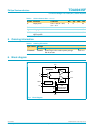
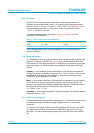
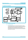
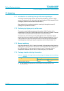
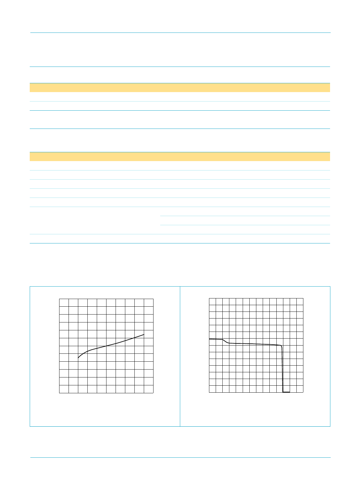
Fig 3. Quiescent supply current as function of supply
voltage.
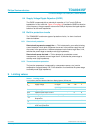
Fig 4. Quiescent supply current as function of mode
voltage.
handbook, halfpage
30
25
20
15
10
5
0
0481216
V
CC
(V)
I
q
(mA)
20
MGU040
handbook, halfpage
28
24
20
12
16
8
4
0
02468
V
MODE
(V)
I
q
(mA)
10 1412
MGU041