


Philips Semiconductors
TDA8943SF
6 W mono Bridge Tied Load (BTL) audio amplifier
Product specification Rev. 02 — 7 April 2000 6 of 20
9397 750 06865
© Philips Electronics N.V. 2000. All rights reserved.
8.4 Supply Voltage Ripple Rejection (SVRR)
The SVRR is measured with an electrolytic capacitor of 10 µF on pin SVR at a
bandwidth of 10 Hz to 80 kHz. Figure 12 on page 10 illustrates the SVRR as function
of the frequency. A larger capacitor value on the SVR pin improves the ripple rejection
behaviour at the lower frequencies.
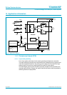
8.5 Built-in protection circuits
The TDA8943SF contains two types of protection circuits, i.e. short-circuit and
thermal shutdown.
8.5.1 Short-circuit protection
Short-circuit to ground or supply line — This is detected by a so-called ‘missing
current’ detection circuit which measures the current in the positive supply line and
the current in the ground line. A difference between both currents larger than 0.4 A,
switches the power stage to standby mode (high impedance).
Short-circuit across the load — This is detected by an absolute-current
measurement. An absolute-current larger than 2 A, switches the power stage to
standby mode (high impedance).
8.5.2 Thermal shutdown protection
The junction temperature is measured by a temperature sensor; at a junction
temperature of approximately 150 °C this detection circuit switches the power stage
to standby mode (high impedance).
9. Limiting values
Table 5: Limiting values
In accordance with the Absolute Maximum Rating System (IEC 60134).
Symbol Parameter Conditions Min Max Unit
V
CC
supply voltage no signal −0.3 +25 V
operating −0.3 +18 V
V
I
input voltage −0.3 V
CC
+ 0.3 V
I
ORM
repetitive peak output current - 2 A
T
stg
storage temperature non-operating −55 +150 °C
T
amb
operating ambient
temperature
−40 +85 °C
P
tot
total power dissipation - 7 W
V
CC(sc)
supply voltage to guarantee
short-circuit protection
-18V