


Philips Semiconductors
TDA8943SF
6 W mono Bridge Tied Load (BTL) audio amplifier
Product specification Rev. 02 — 7 April 2000 14 of 20
9397 750 06865
© Philips Electronics N.V. 2000. All rights reserved.
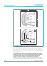
14.2 Thermal behaviour and heatsink calculation
The measured maximum thermal resistance of the IC package, R
th(j-mb)
is 18 K/W.
A calculation for the heatsink can be made, with the following parameters:
T
amb(max)
=50°C
V
CC
= 12 V and R
L
=8Ω
T
j(max)
= 150 °C.
R
th(tot)
is the total thermal resistance between the junction and the ambient
including the heatsink. In the heatsink calculations the value of R
th(mb-h)
is ignored.
At V
CC
=12VandR
L
=8Ω the measured worst-case sine-wave dissipation is 3.8 W;
see Figure 11. For T
j(max)
= 150 °C the temperature raise – caused by the power
dissipation – is: 150 – 50 = 100 °C.
P × R
th(tot)
= 100 °C
R
th(tot)
= 100/3.8 = 26.3 K/W
R
th(h-a)
=R
th(tot)
–R
th(j-mb)
= 26.3 – 18 = 8.3 K/W.
The calculation above is for an application at worst-case sine-wave output signals. In
practice music signals will be applied, which decreases the maximum power
dissipation to approximately half of the sine-wave power dissipation (see
Section 8.2.2). This allows for the use of a smaller heatsink:
P × R
th(tot)
= 100 °C
R
th(tot)
= 100/1.8 = 55.5 K/W
R
th(h-a)
=R
th(tot)
–R
th(j-mb)
= 55.5 – 18 = 37.5 K/W.
To increase the lifetime of the IC, T
j(max)
should be reduced to 125 °C. This requires a
heatsink of approximately 24 K/W for music signals.
15. Test information
15.1 Quality information
The
General Quality Specification for Integrated Circuits, SNW-FQ-611D
is
applicable.
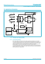
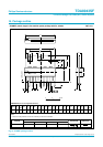
15.2 Test conditions
T
amb
=25°C; V
CC
= 12 V; f = 1 kHz; R
L
=8Ω; audio pass band 22 Hz to 22 kHz;
unless otherwise specified.
Remark: In the graphs as function of frequency no bandpass filter was applied; see
Figure 7 and 12.