12 C1641M-A (3/05)
Installation
PACKAGE CONTENTS
The following items are supplied:
• With the FT8301 transmitter:
1 Regulated switching power supply with four plug adapters (North American,
Australian, U.K., and European configurations); 100-240 VAC input, 12 VDC output
1 FT8301/FR8301 Fiber Transmitter and Receiver Installation manual (this manual)
• With the FR8301 receiver:
1 Regulated switching power supply with four plug adapters (North American,
Australian, U.K., and European configurations); 100-240 VAC input, 12 VDC output
1Wall clip with two 4-40 x .250-inch Phillips pan head screws with lock washers
(for attachment of single module to wall)
1 FT8301/FR8301 Fiber Transmitter and Receiver Installation manual (this manual)
MOUNTING
The miniature FT8301 transmitter is a standalone module that can be placed on a desktop or can
be mounted to a wall. The FR8301 receiver, which is standard in size, can be mounted into a rack
or can be used as a standalone module by being placed on a desktop or mounted to a wall.
MOUNTING THE FT8301 TRANSMITTER
NOTE:
Before mounting the FT8301 transmitter to a wall, ensure that the positioning of
the unit allows viewing of the front-panel LEDs and provides space for making the
various rear-panel cable connections.
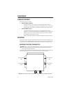
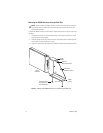
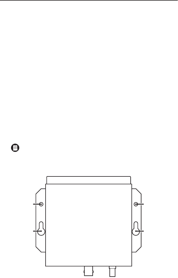
To mount the FT8301 transmitter to a wall, attach the unit using two screws (not provided) using
either the wall-mounting holes or the wall-mounting keyholes (refer to Figure 6).
Figure 6.
Mounting the FT8301 Transmitter to a Wall (Top View of FT8301 Transmitter)
WALL-MOUNTING
KEYHOLE
WALL-MOUNTING
HOLE
WALL-MOUNTING
HOLE
WALL-MOUNTING
KEYHOLE


