


10
Rotate the data wheel to scroll across the screen and push the
wheel to select and confirm.
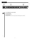
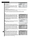
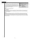
A B C & D INPUTS:
Input sensitivity switches between –10 dBV or +4 dBV inputs.
The +4 dB position should be considered the “normal” position
and should be used with professional systems. The -10 dB
position allows the unit to be driven with “hi-fi” level equipment or
directly from a CD player.
Mute toggle on/off.
Analog/digital operation is selectable on input A.
Level controls digital processing headroom and is adjustable from 0 dB through –100 dB. This adjustment is
best left as high as possible but may be adjusted as necessary.
Trim is variable from –6 dB to +6 dB and is used to match analog input sensitivity as necessary.
Exit this screen by selecting “Done” and pressing the data wheel or pressing the “setup” button.
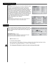
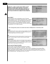
ST/M:
Toggles between Stereo and Mono. Selecting Stereo associates
the A/B channel inputs. It does not affect the output channels.
When engaged in “stereo” adjusting a parameter on channel
A will make a corresponding adjustment on Ch B. This may be
most useful when adjusting PEQs, Delay or Dynamic settings.
Preliminary adjustments can be made to both channels in this
manner and then the switch can be toggled to mono allowing
further independent adjustment of single inputs. The switch
may be toggled again to link up the dynamic sections for stereo
tracking of the comp/limiters.
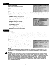
MIC:
Allows engaging the +48 V phantom power as well as adjusting
the Mic gain range from 23 dB to 67 dB of gain. Select “done” or
press “setup” to escape to the main screen.
GEN:
This screen selects the parameters for the signal generator.
Pink, White or Sine may be selected. When Sine is selected the
frequency of the sine wave may be adjusted for 20 Hz to 20 kHz.
The output level may be adjusted by highlighting the fader graphic
and adjusting the Level control. An In/Out button is provided
to turn on and off the generator. The screen may be exited by
selecting “done” or pressing the “setup button. The Generator
must be assigned to an output of your choice with the Matrix. A
single Band pass filter can also be assigned to that output and
the skirts may be adjusted to provide limited bandwidth noise for
testing purposes.
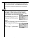
MATRIX:
The matrix provides the method to assign inputs to outputs. In
the default configuration NO SIGNAL IS PASSED through the
unit until some selection in the matrix is made. This prevents
potentially destructive signals from reaching the wrong outputs.
The inputs are represented by the rows and the outputs by
the columns. Most users will commonly assign crossovers in
the setup screen so that only a single input assignment will be
necessary. In addition to the line inputs the Mic and GEN inputs
are assigned in this screen. To continue from the matrix you must
exit from the upper left or the lower right squares.
Setup/Configuration Screen