


8
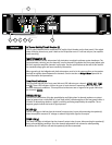
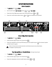
MMOODDEE SSeelleecctt SSwwiittcchh ((88))
The rear panel MODE Select Switch determines whether the amplifier is in stereo, parallel, or
bridged mono mode. Do not operate the Mode Select Switch with the amplifier powered on. See
the sections on Stereo and Bridged Mono Mode for more information.
AAMMPP FFUUNNCCTTIIOONN SSwwiittcchh ((99))
The rear panel AMP FUNCTION Select Switch determines whether the associated channel is
connected for full range operation or to the crossover high frequency or low frequency outputs.
CCRROOSSSSOOVVEERR AAddjjuussttmmeenntt KKnnoobb ((1100))
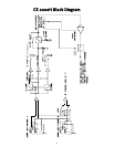
The CS 2000H is equipped with two independent‚ two-way crossovers adjustable from 40 Hz to
300 Hz. These crossover frequencies are appropriate for use with a subwoofer system. The output
of these crossovers is selected by the MODE switch and connected to the corresponding amplifier
channel. Frequencies above the knob setting will be connected to the corresponding channel
when the MODE switch is in the HIGH PASS position. Frequencies below the knob setting will be
connected to the corresponding channel when the MODE switch is in the LOW PASS position. The
FULL RANGE position bypasses the crossover.
LLOOWW CCUUTT AAddjjuussttmmeenntt KKnnoobb ((1111))
The CS 2000H is equipped with two independent low frequency filters. These filters are adjustable
from 20 Hz to 100 Hz and are designed to reduce frequencies below those capable of being
produced by the loudspeakers, or to reduce room “rumble.” Frequencies below the knob setting
of the corresponding channel will be attenuated.
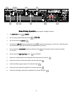
RReeaarr PPaanneell
8 9 10 11
12
13
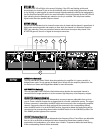
DDDDTT LLEEDD ((66))
A channel’s DDT LED will light at the onset of clipping. If the LED’s are flashing quickly and
intermittently, the channel is just at the clip threshold, while a steady, bright glow means the amp
is clip limiting, or reducing gain to prevent severely clipped waveforms reaching the loudspeakers.
See the Distortion Detection section for more information. During initial power up the DDT LED will
light indicating that the RampUp gain reduction circuitry is activated. This will prevent sudden
signal bursts when the speaker relays are closed.
AACCTTIIVVEE LLEEDD ((77))
The ACTIVE LED indicates that its channel’s output relay is closed and the channel is operational. It
lights under normal operation and remains on even when the channel is in Distortion Detection
(DDT) gain reduction. These are protection features which leave the output relay closed. If the
ACTIVE LED goes off, there is no signal at the output connectors.
14