


6
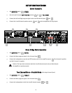
CCoonnnneeccttiinngg IInnppuuttss
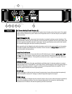
Input connections are made via the 3-pin XLR (pin 2+) or 6.3 mm plug “Combi” connectors on the
rear panel of the amplifier. The inputs are actively balanced. Pinout and polarity of connection
cables should be configured correctly (refer to the rear panel of the unit). The input overload
point is high enough to accept the maximum output level of virtually any signal source.
CCoonnnneeccttiinngg OOuuttppuuttss
All models have two output (speaker) connections per channel. Cables can be connected with
banana plugs, spade lugs, or bare wire to the 5-way binding posts. The preferred connection
method is via the Speakon connectors. Pin connections are noted on the rear panel of the unit.
CCoonnnneeccttiinngg PPoowweerr
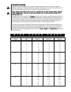
The CS2000H power requirements are rated at 1/8 power (typical music conditions) and 1/3
power (extreme music conditions). The maximum power current draw rating is limited only by the
front panel circuit breaker. Consult the specifications in this manual for figures on the current
that this amplifier will demand. Make sure the mains voltage is correct and is the same as that
printed on the rear of the amplifier. Damage caused by connecting the amplifier to improper AC
voltage is not covered by any warranty. Unless otherwise specified when ordered, Peavey
amplifiers shipped to customers are configured as follows:
North America: 120 VAC/60 Hz
Europe, Asia, Australia: 230/240 VAC/50 Hz
South America: 120 VAC/60 Hz or 240 VAC/50 Hz
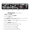
SStteerreeoo
For stereo (dual channel) operation, turn the amplifier off and set the mode select switch to the
stereo position. In this mode, both channels operate independently of each other, with their
input attenuators controlling their respective levels. Thus, a signal at Channel A’s input produces
an amplified signal at Channel A’s output, while a signal at Channel B’s input produces an
amplified signal at Channel B’s output.
PPaarraalllleell
For parallel (dual-channel/single input) operation, turn the amplifier off and set the mode switch
in the parallel position; both amplifier channels are then driven by the signal at Channel A’s
input. No jumper wires are needed. Output connections are the same as in the stereo mode. In
the parallel mode, only Channel A’s input is active; Channel B’s is out-of-circuit. Both input
attenuators remain active, allowing you to set different levels for each channel. Power and other
general performance specifications are the same as in the stereo mode.
BBrriiddggeedd MMoonnoo
Both amplifier channels can be bridged together to make a very powerful single-channel
monaural amplifier. Use extreme caution when operating in the bridged mode; potentially lethal
voltage may be present at the output terminals. To bridge the amplifier, set the rear panel mode
select switch to the bridge position. Apply the signal to Channel A’s input and connect the
speakers across the hot outputs (the “+” binding posts of Channels A and B).
Unlike the stereo and parallel modes, in which one side of each output is at ground, in the
bridged mode both sides are hot. Channel A’s side is the same polarity as the input. For proper
operation, both input attenuators must be in the same position. This keeps the load balanced
between the channel outputs. As in the parallel mode, only Channel A’s input is active. If an
output patch panel is used, all connections must be isolated from each other and from the panel.
The recommended minimum nominal load impedance in the bridged mode is 4 Ohms (equivalent
to driving both channels at 2 Ohms). Driving bridged loads of less than 4 Ohms will activate the
DDT circuitry resulting in a loss of power, and may also cause a thermal overload.
OOppeerraattiioonn MMooddeess