


ALARM RECOVER OUT
14
MODE
ON
Termination
Unit Address/Initializing
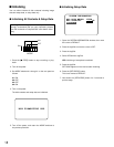
Alarm Out Polarity
1234 56
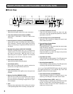
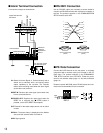
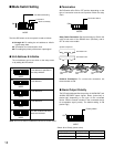
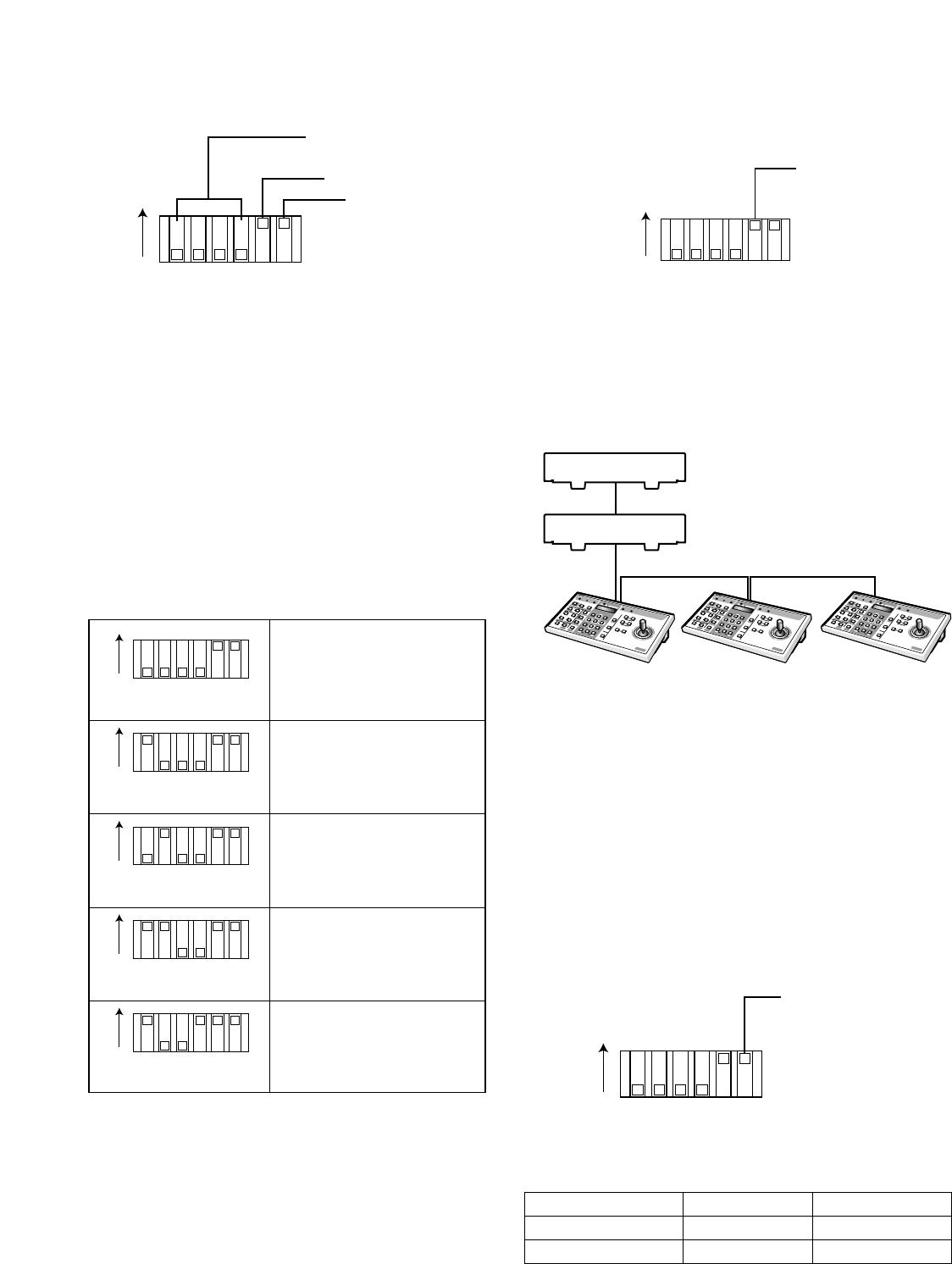
■ Mode Switch Setting
The 6-bit DIP switch on the rear panel is used as follows.
#1 through #4: For setting the unit address or initializ-
ing the setup data
#5: Termination for communication lines
#6: For setting the polarity of the alarm output signal
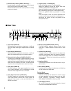
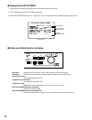
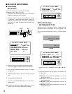
● Unit Address & Initialize
The unit address can be set either on the setup menu
or by setting this DIP switch.
MODE
ON
1234 56
MODE
ON
1234 56
MODE
ON
1234 56
MODE
ON
1234 56
MODE
ON
1234 56
Unit address is specified in
the setup window.
Unit address 1
Unit address 2
Unit address 3
All disk contents and setup
data are initialized.
Note: Do not use switch combinations other than shown above.
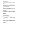
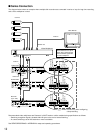
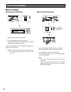
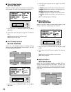
● Termination
Set DIP switch #5 to ON or OFF position depending on the
type of connection and the unit's position within the daisy
chain.
Daisy Chain Connection: Set the termination to ON for the
units at both ends of the RS-485 chain (PS
•
Data), and to
OFF for units in the middle.
Homerun Connection: For a one-to-one connection, set
the termination to ON.
ON
Termination Switch
MODE
1234 56
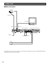
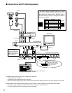
System Component
Termination ON
Termination OFF
Termination
OFF
Termination
OFF
Termination
ON
S
y
s
t
e
m
C
o
n
t
r
o
l
l
e
r
W
U
-
C
U
360360
For PS.D
.L
IN
K
8
9
7
0
4
5
6
2
3
1
S
y
s
t
e
m
C
o
n
t
r
o
l
l
e
r
W
U
-
C
U
360360
F
or PS
.D
.LIN
K
8
9
7
0
4
5
6
2
3
1
S
y
s
t
e
m
C
o
n
t
r
o
l
l
e
r
W
U
-
C
U
360360
F
or
P
S.D
.L
INK
8
9
7
0
4
5
6
2
3
1
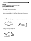
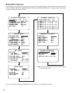
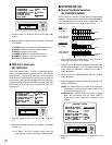
● Alarm Output Polarity
The DIP switch #6 specifies the polarity of ALARM OUT and
ALARM RECOVER output signals. Select [active-low] or
[active-high] depending on the type of the connected
device. See the manual included in the connected device
for acceptable signal polarity. The default setting is ON
[active-high].
MODE
ON
Polarity switch
1234 56
Switch #6 vs Polarity (when active)
ALARM OUT
ON (active-high) OFF (active-low)
Open-collector low
Open-collector low
+12 V DC
+5 V DC