


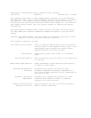
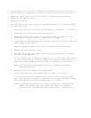
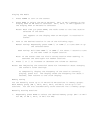

||||
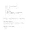
||||__Black-----------GROUND (-)---------------(To Chassis Ground)
|||
|||___Red-------------POWER LEAD B+ -----------(To ACC)
||
||____Blue/White------AMP REMOTE TURN ON ------(To Optional Equipment)
|
|_____Yellow----------CLOCK MEMORY ------------(To Battery +)
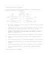
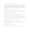
1. Disconnect the cable from your vehicle battery's negative (-)
terminal.
2. Connect the black ground wire to a chassis ground, such as a metal
screw attached to a metal part of the vehicle's frame. Be sure that
the screw is not insulated from the chassis by a plastic part.
3. Connect the red power wire (with in-line fuse holder) to a point in
your vehicle's fuse block that has power only when you turn the
vehicle's key to either the accessory (ACC) or START position.
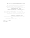
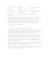
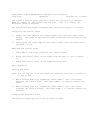
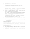
Harness with 14-pin Connector
________
|________|
|
|_____Red_____POWER LEAD B+ (To ACC or START)
This connection turns on the stereo when you turn on the ignition or
turn the key to ACC, and turns off the stereo when you turn off the
ignition. This prevents your vehicle's battery from being drained if
you leave the stereo on when you turn off the ignition.
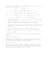
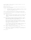
4. Connect the yellow power/memory wire (with in-line fuse holder) to
your vehicle battery's positive (+) terminal or to a point in your
vehicle's fuse block that provides a continuous source of 12 volts.
This connection provides power for the stereo's components (such as
the clock), and continuous power for the stereo's memory when the
ignition is turned off.
5. Connect the blue/white wire to any optional equipment, designed to run
from a switched source, that you want the stereo to turn on and off
(such as a booster or a power antenna).
This wire does not provide power to the components. It simply turns
them on or off. If you do not use this wire, secure it with a wire tie
and do not let it touch metal.