


39
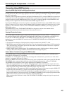
Connecting AV Components
—Continued
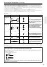
• When connecting a MD recorder, DAT deck or CD recorder to the TX-NR1000/TX-NR5000E, make connections
using digital or analog terminals. Before making connections, refer to page 30 for correct connections.
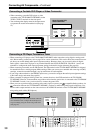
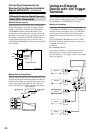
• Connect a cassette or DAT tape deck to TAPE1, and an MD or CD recorder to TAPE 2.
• When you connect a cassette deck to the TX-NR1000/TX-NR5000E, be sure to use only analog audio terminals. In
the initial settings, no terminal of this unit is assigned to a REC terminal of the cassette deck. To achieve the assign-
ment, connect the REC terminal of the cassette deck to any of the AUDIO OUT 1 to 5 terminals and set the terminal
to “Tape 1 Rec Out” in the Audio Output Assign sub-menu (See page 91). In addition, you can switch the input source
“TAPE2” to MD or CDR. Press the [TAPE 2] button on the front panel to display “TAPE 2,” then press the [TAPE 2]
button again and hold it for 3 seconds. This changes the display to “MD.” If you wish to change it to “CDR,” release
the button once, and press and hold it again for 3 seconds. This operation enables you to operate Onkyo’s MD or CD
recorders with the remote controller of this unit (Please note that the connection is required).
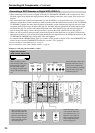
• When connecting to other terminals, remember to configure the audio input assignment in the Audio Assign sub-
menu (See page 94) and the audio output assignment in the Audio Output Assign sub-menu (See page 91).
• You can change the display name for the input source to represent the actual connected device (See page 97).
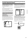
• When you want to perform analog recording of an audio signal or operate your -compatible Onkyo products via
connections between the TX-NR1000/TX-NR5000E, you have to make analog audio signal connections. Con-
nect the audio output terminals on the source device to the AUDIO IN terminals on the TX-NR1000/TX-NR5000E
using analog audio cables (RCA/phono).
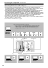
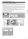
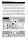
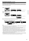
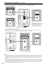
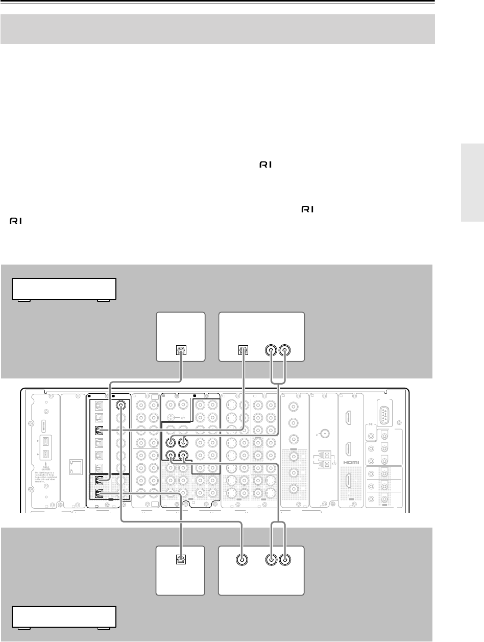
Example for connecting with the TAPE 1 as input
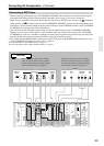
Example for connecting to the TAPE 2 as input
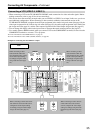
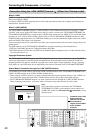
Connecting a Recording Device such as MD Recorder, DAT Deck, CD Recorder
or Cassette Deck
REMOTE
CONTROL
MAIN
ZONE
3
ZONE
2
OUT
IN
FRONT
L
CENTERFRONT
R
SURR BACK
R
(
ASSIGNABLE
)
SURR BACK
L
(
ASSIGNABLE
)
SURR
R
SURR
L
IR
12V
TRIGGER
OUT
RS
232
A B C D F
G
H I J K L
PRE
OUT
A
(
SINGLE
)
A
C
B
D
E
200mA MAX.
100mA MAX.
100mA MAX.
100mA MAX.
100mA MAX.
“Net
-
Tune”
is
a
trademark
of
Onkyo
Corporation.
ETHERNET
(
Net
-
Tune
)
2 2
1 1
66
55
44
3 3
22
1 1
C D
DIGITAL IN DIGITAL IN
OPTICAL COAXIAL
OUT
SBR SBL
SR SL
SUB C
FR FL
SBR SBL
SR SL
SUB C
FR
FL
E
MULTI
-
CH
IN
1
MULTI
-
CH
IN
2
AUDIO IN
1
3
2
1
PH
2
3
9
8
7
6
5
4
4
5
LRRL
OUT
LR
LR
R L
F
G
L
IN
1
IN
2
HDMI, the HDMI logo
is a trademark
or registered
trademarks of HDMI
Licensing LLC.
OUT
HDMI
S
VIDEO VIDEO
IN
1
IN
2
3
2
1
Y
P
B
PR
COMPONENT
VIDEO
IN
3
I
6
5
4
Y
P
B
PR
2
1
4
3
S VIDEOS VIDEO VIDEOVIDEO
OUT OUT
OUT
1
J
Y
P
B
PR
Y
P
B
PR
COMPONENT VIDEO
IN
4
OUT
2
K
ANTENNA
FM
75
AM
G
H
GND
R
L
R
L
ANALOG
DIGITAL
OPTICAL
AUDIO IN
AUDIO OUT
DIGITAL
OPTICAL
AUDIO OUT
ANALOG
AUDIO OUT
DIGITAL
OPTICAL
AUDIO IN
DIGITAL
COAXIAL
AUDIO OUT
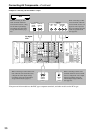
When connecting to other digital audio
terminals or to other analog audio output
terminals, configure the audio output set-
tings accordingly using the Audio Output
Assign sub-menu (See page 91).
When connecting to other audio
terminals within the same termi-
nal section, configure the audio
input settings accordingly using
the Audio Assign sub-menu (See
page 94).
When connecting to other digital audio
terminals or to other analog audio output
terminals, configure the audio output set-
tings accordingly using the Audio Out-
put Assign sub-menu (See page 91).
When connecting to other audio
terminals within the same termi-
nal section, configure the audio
input settings accordingly using
the Audio Assign sub-menu (See
page 94).
Cassette deck or DAT deck
MD recorder or CD recorder