


24
Connections
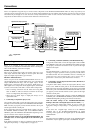
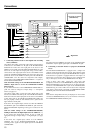
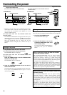
The TX-SR701/701E/601/601E is equipped with AC mains outlets
for connecting the power cords from other devices so that their
power is supplied through the TX-SR701/701E/601/601E. By doing
this, you can leave the connected device turned on and have the
STANDBY/ON button on the TX-SR701/701E/601/601E turn on
and off the device together with the TX-SR701/701E/601/601E.
The shape, number, and total capacity of the AC outlets may
differ depending on the area of purchase.
Caution:
Make sure that the total capacity of the components connected to
the TX-SR701/701E/601/601E does not exceed the capacity that is
printed on the rear panel (e.g., TOTAL 120W).
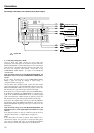
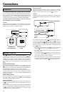
The terminal on the TX-SR701/701E/601/601E is for
connecting other Onkyo components equipped with the same
terminal. When a component is connected to the terminal, it can be
operated by the remote controller supplied with the TX-SR701/
701E/601/601E. In addition, when you connect a component to the
terminal, you can also perform the system operations given
below.
Power on/ready function
When the TX-SR701/701E/601/601E is in the standby state, if an
-connected component is turned on, the TX-SR701/701E/601/
601E also turns on and the input source selected at the TX-SR701/
701E/601/601E automatically switches to that component.
Be aware that this function will not work if the power cord for the -
connected component is connected to the AC OUTLET on the TX-
SR701/701E/601/601E, or if the TX-SR701/701E/601/601E has
already been turned on.
Direct change function
When the play button is pressed at an -connected component,
the input source selected at the TX-SR701/701E/601/601E
automatically changes to that component.
Power off function
When the TX-SR701/701E/601/601E is placed in the standby state,
all -connected components are also automatically put into the
standby state.
Also, if you press the ON button on the TX-SR701/701E/601/601E
remote controller while the TX-SR701/701E/601/601E is turned on,
all -connected components (DVD players, CD players, MD
recorders, tuners, etc.) are also turned on.
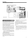
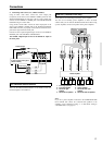
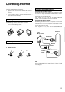
AC OUTLETS
REMOTE CONTROL
AC OUTLETS
SWITCHED
TOTAL 100W MAX.
AC 230-240
V 50
Hz
AC OUTLETS
AC
120
V 60
Hz
SWITCHED
TOTAL 120W 1A MAX.
European and
some Asian models
USA and Canadian
models
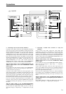
Dimmer function
The Dimmer function (display brightness adjustment) of the TX-
SR701/701E/601/601E can be used to synchronize the display
brightness on the connected device using the connection.
Caution:
If an MD recorder is connected to the TAPE jack on the TX-SR701/
701E/601/601E, switch the Input Selector from TAPE to MD (see
page 43).
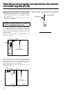
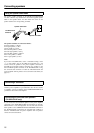
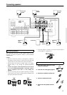
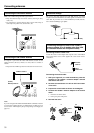
To connect components using the terminal, simply connect a
remote control cable from this terminal to the terminal of
the other component. An remote control cable with a 1/8-inch
(3.5-mm) miniature two-conductor plug comes with every cassette
tape deck, compact disc player, MD recorder, and DVD player that
has an terminal.
• When performing operations with -connected components
using the system, do not use the remote zone (Zone 2) .
• For remote control operation, the audio connection cables must
also be connected.
• If a component has two terminals, you can use either one to
connect to the TX-SR701/701E/601/601E. The other one can be
used to daisy chain with another component.
• With Onkyo DVD players, you can enter the pre-program code
so that you can operate the DVD player directly with the remote
controller without connecting the terminals (see page 67).
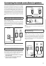
TX-SR701/701E/601/601E
connector
Ex: Onkyo CD player
Ex: Onkyo cassette tape
deck
connector