


17
Connections
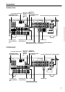
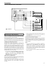
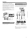
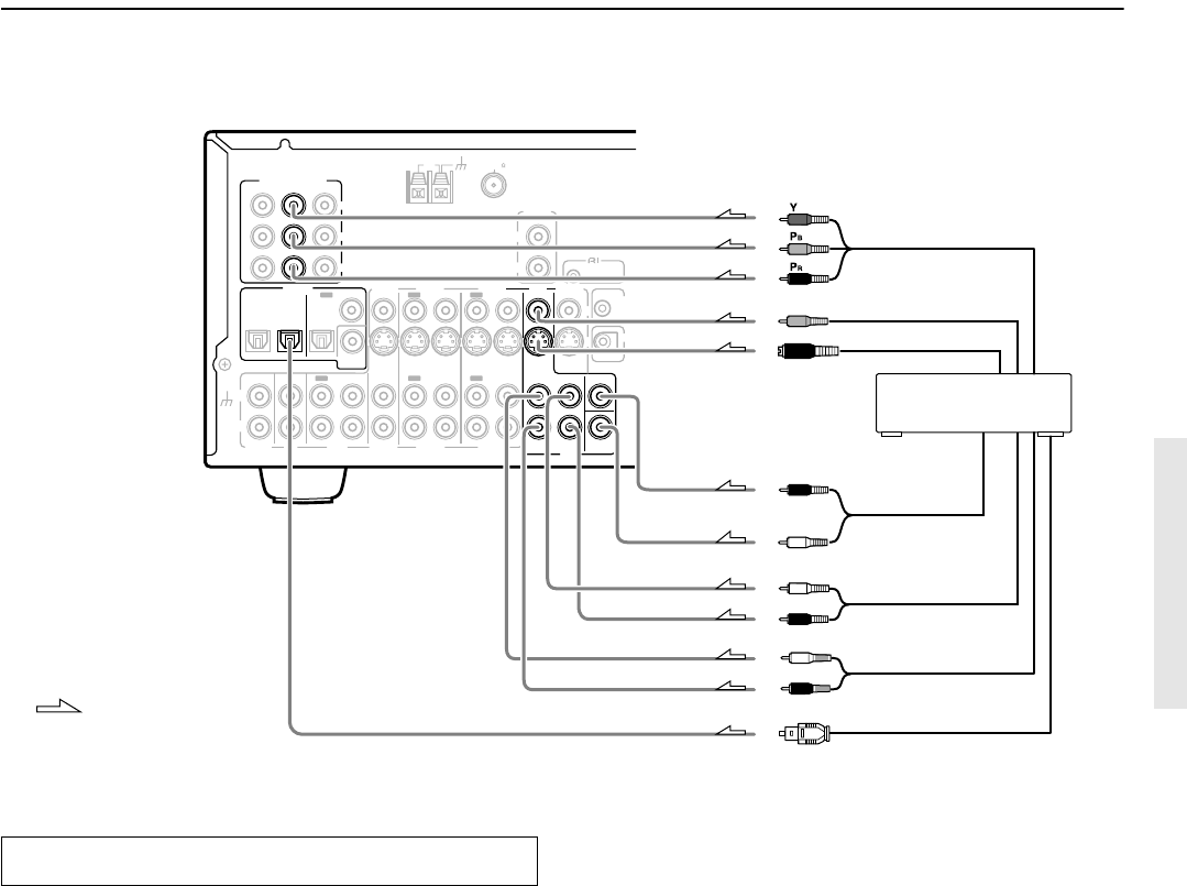
Connecting a DVD Player with 5.1-Channel Output
INPUT 1
INPUT 2
OUTPUT
COMPONENT VIDEO
Y
OPTICAL
1
2
IN
IN
IN
IN
FRONT
SURR
CENTER
SUB
WOOFER
VIDEO 2
VIDEO 1
VIDEO 2
DVD
MONITOR
OUT
DVD
TAPE
IN
L
R
VIDEO 3
VIDEO 1
V
VIDEO 3
OPTICAL
IN
IN
IN
ININ
IN
OUTOUT
OUTOUTOUT
S
DIGITAL
OUT
CD
COAXIAL
L
R
IN
GND
PHONO
COAXIAL
PR
PB
12
V
TRIGG
OUT
ZONE 2
IR IN
12
V
TRIGG
OUT
ANTENNA
FM
75
AM
REMOTE
CONTROL
R
L
ZONE 2
LINE OUT
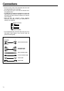
: Signal flow
4. DVD player (DVD)
Component video output
R (red)
L (white)
Digital audio output
(optical)
R (red)
L (white)
Analog audio output
(front L/R)
Analog audio output
(surround L/R)
Analog audio output
(subwoofer)
Analog audio
output (center)
Video output
S video output
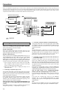
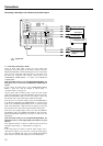
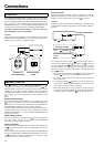
Below is an example of how you can connect your video
components to the TX-SR701/701E/601/601E. Refer to the diagram
above for the following connection examples.
Video signal will be output if you use any one of COMPONENT, S,
or composit terminals. However, you are recommended to match the
type of video terminals for connection between video devices (ex.
DVD player and VCR), TX-SR701/701E/601/601E and TV/monitor.
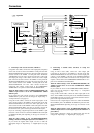
COMPONENT VIDEO INPUT/OUTPUT
For DVD players or other devices that have component video
connectors, the TX-SR701/701E/601/601E has two banks of
component video input connectors (Y, PB, PR) for direct
component video input. TX-SR701/701E/601/601E also has one
bank of component video output connectors for direct component
video output to the matrix decoder of a television, projector, or
other display device. By sending the pure component video signal
directly, the signal forgoes the extra processing that normally would
degrade the image. The result is vastly increased image quality, with
incredibly lifelike colors and crisp detail.
• The signal that comes in from COMPONENT VIDEO INPUT
is only sent to COMPONENT VIDEO OUTPUT. When
connecting a video player to the COMPONENT VIDEO
INPUT jacks, be sure to connect your television to the
COMPONENT VIDEO OUTPUT jacks.
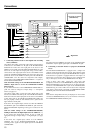
VIDEO IN/OUT, S VIDEO IN/OUT
These are the video inputs and outputs. On the rear panel, there are
four video inputs and two video outputs and each one includes both
composite video and S video configurations.
Connect VCRs, VTRs, LD players, DVD players, and other video
components to the video inputs. Connect VCRs, VTRs, and other
recording components to the video outputs to make video
recordings.
Connecting your video components
• When connecting a VCR or other video component, make sure
you connect its audio and video leads to the same bank (e.g.,
both to VIDEO 3).
• The VIDEO 4 inputs are located on the front panel.
The flow of the video signals is as follows:
The signal that comes in from a VIDEO IN jack is sent to both the
VIDEO OUT and S VIDEO OUT jacks. The signal that comes in
from a S VIDEO IN jack is sent to both the S VIDEO OUT and
VIDEO OUT jacks. It is not necessary to make both video and S
video connections.
Notes:
• If your video output device (e.g., television or projector) is
connected only to the MONITOR OUT VIDEO jack,
MONITOR OUT S VIDEO jack, or both, and the video signal
from the source component is input through the component
video connectors, no picture will appear. Video sources input
from the component video connectors can only be output from
the component video connectors.
• For more information about the DIGITAL INPUT/OUTPUT
jacks, see page 16.