


18
Connections
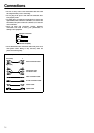
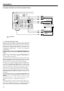
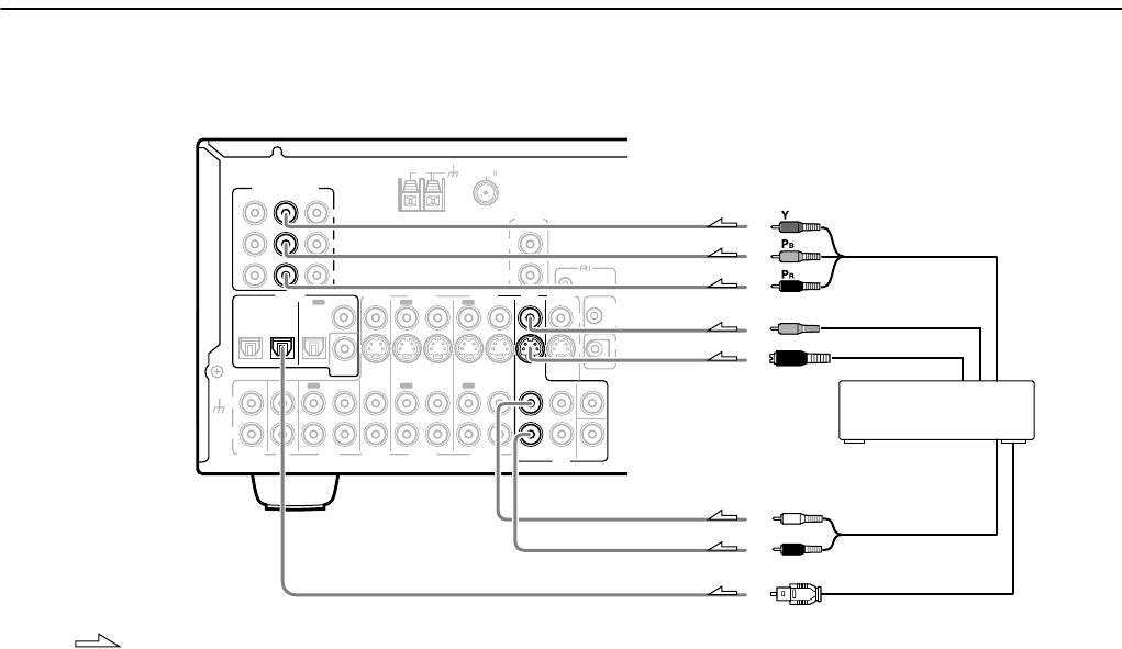
Connecting a DVD Player with 2-Channel (L/R) Audio Output
4. Connecting a DVD player (DVD)
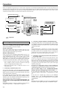
Using an RCA video cable, connect the video output jack
(composite) of the DVD player to the DVD V IN jack of the TX-
SR701/701E/601/601E. Or if the DVD player has an S video output
jack, connect it to the DVD S IN jack with an S video cable. Or if
the device has component video outputs, connect them to the
COMPONENT VIDEO INPUT 1 or 2 jacks on the TX-SR701/
701E/601/601E.
With the initial settings of the TX-SR701/701E/601/601E, the
DVD input source is set for the COMPONENT VIDEO INPUT
1 jacks.
If you connect the DVD player to the COMPONENT VIDEO
INPUT 2 jacks, this must be changed at “Input Setup” →
“Component Video” (see page 53).
Using an RCA audio connection cable, connect the audio output
jacks of the DVD player to the DVD FRONT L/R jacks of the TX-
SR701/701E/601/601E. Make sure that you properly connect the
left channel to the L jack and the right channel to the R jack.
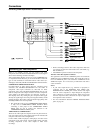
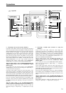
If the device has a 5.1-channel output, connect the DVD FRONT L/
R, SURR L/R, CENTER, and SUBWOOFER (5.1-channel input)
jacks of the TX-SR701/701E/601/601E to the 5.1-channel output
jacks of the DVD player. Make sure that you properly connect the
left channels to the L jacks and the right channels to the R jacks.
If the device has a digital output, connect it to either the DIGITAL
IN COAXIAL jack or the DIGITAL IN OPTICAL jack of the TX-
SR701/701E/601/601E depending on the type of connector on the
DVD player.
With the initial settings of the TX-SR701/701E/601/601E, the
DVD input source is set for digital input at the OPTICAL 1 jack
(OPT 1).
If the digital connection is made at a different jack, this must be
changed at “Input Setup” → “Digital Input” (see page 52).
Note:
If the DVD player has both 5.1-channel audio outputs and 2-
channel audio outputs, and you want to connect the DVD player
only using the FRONT L/R jacks on the TX-SR701/701E/601/
601E, use the 2-channel audio output jacks on the DVD player.
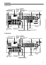
INPUT 1
INPUT 2
OUTPUT
COMPONENT VIDEO
Y
OPTICAL
1
2
IN
IN
IN
IN
FRONT
SURR
CENTER
SUB
WOOFER
VIDEO 2
VIDEO 1
VIDEO 2
DVD
MONITOR
OUT
DVD
TAPE
IN
L
R
VIDEO 3
VIDEO 1
V
VIDEO 3
OPTICAL
IN
IN
IN
ININ
IN
OUTOUT
OUTOUTOUT
S
DIGITAL
OUT
CD
COAXIAL
L
R
IN
GND
PHONO
COAXIAL
PR
PB
12
V
TRIGG
OUT
ZONE 2
IR IN
12
V
TRIGG
OUT
ANTENNA
FM
75
AM
REMOTE
CONTROL
R
L
ZONE 2
LINE OUT
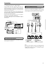
: Signal flow
4. DVD player (DVD)
Component video output
Video output
S video output
R (red)
L (white)
Analog audio output
Digital audio output
(optical)