


13
Operation
Other Information
Before using
PreparationsConnections
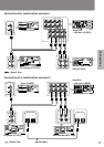
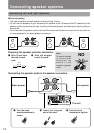
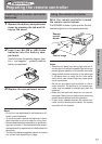
Connecting the cables
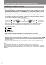
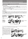
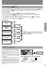
If your other components are made by ONKYO and those components are equipped with connec-
tors, you can control the
-connected components with the supplied remote controller.
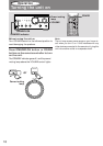
Before connecting
• The unit must be connected in the
system hookups for control operations.
• Each component has two
connectors. There is no difference between these connectors.
• The components may be connected in any order.
• The hookups on the previous page are necessary independently of the
system hookups.
The illustration below is an example of a
hookup.
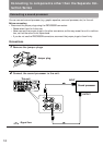
Connections
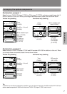
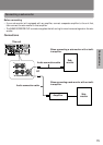
AC outlet connection
You can connect the power cord from an-
other audio device to the rear of the A-905X.
Since the AC outlet on the unit is a
SWITCHED type outlet, you can use the
POWER switch to turn on/off the power
to both the A-905X and the connected
audio device.
The shape and capacity of the AC outlet
may differ depending on the area of pur-
chase. Make sure that the capacity of other
components connected to this unit does not
exceed the capacity that is printed on the
rear panel.
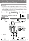
cable (supplied with every ONKYO compo-
nent that has
connectors except for the am-
plifier and receiver)
MD recorder
Tuner
Stereo cassette
tape deck
Amplifier
– this unit
CD player
L
R
IN(PLAY)
L
R
LINE-1LINE-2
OUT
IN
L
R
TAPE
SPEAKERS
REMOTE
CONTROL
OUT(REC)
IN(PLAY)
OUT(REC)
CD
TUNER
PROCESSOR
MD
L
R
SUBWOOFER
PRE OUT
AC OUTLET
AC230V 50Hz
SWITCHED
100W MAX.
A-905X
MODEL NO.
INTEGRATED
STEREO AMPLIFIER
RATING;
Capacity is total
120 watts.
120 V, 60 Hz models230 V, 50 Hz models
Capacity is total
100 watts.