


11
Operation
Other Information
Before using
PreparationsConnections
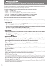
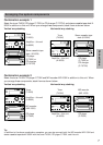
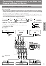
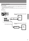
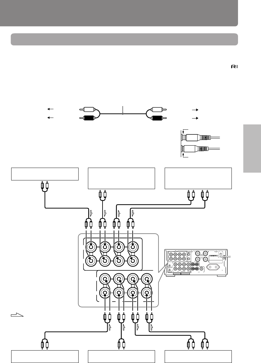
Connecting to components other than the
Separate Collection Series
Video cassette
recorder
Stereo cassette tape
deck
PLAY
OUTPUT
REC
INPUT
AUDIO
OUT
AUDIO
OUT
OUTPUT
REC
INPUT
PLAY
OUTPUT
OUTPUT
: Signal flow
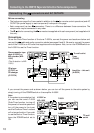
Tuner
CD player
MD recorder
Amplifier
– this unit (A-905X)
LD player
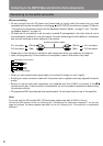
Connecting audio/video equipment to audio cables
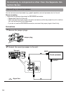
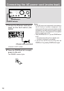
Before connecting
• Do not connect the AC power cord (mains lead) to the wall outlet (the mains) until you have com-
pleted all the other connections including the sound processor connections on the next page, the
connections on page 13, and the speaker connections on page 14.
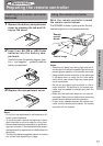
• On each pair of connectors, a red connector (marked R) corresponds to the right channel, and a
white connector (marked L) to the left channel.Connect white plugs of audio cables to L connectors
and connect red plugs of audio cables to R connectors .
Improper connection
Insert completely
• Please refer to the instruction manual for each component
when you make any connections.
• Insert the plug securely. If the connection is incomplete, noise
or malfunction may result.
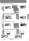
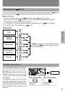
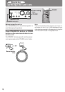
Connections
L
R
IN(PLAY)
L
R
LINE-1LINE-2
OUT
IN
L
R
TAPE
SPEAKERS
REMOTE
CONTROL
OUT(REC)
IN(PLAY)
OUT(REC)
CD
TUNER
PROCESSOR
MD
L
R
SUBWOOFER
PRE OUT
AC OUTLET
AC230V 50Hz
SWITCHED
100W MAX.
A-905XMODEL NO.
INTEGRATED
STEREO AMPLIFIER
RATING;
IN(PLAY)
L
R
LINE-1LINE-2
L
R
TAPE
OUT(REC)
IN(PLAY)
OUT(REC)
CD
TUNER
MD
L
R
Audio connection cable
To L connector (White)
To R connector
(Red)
(White)
To L connector
(Red)
To R connector